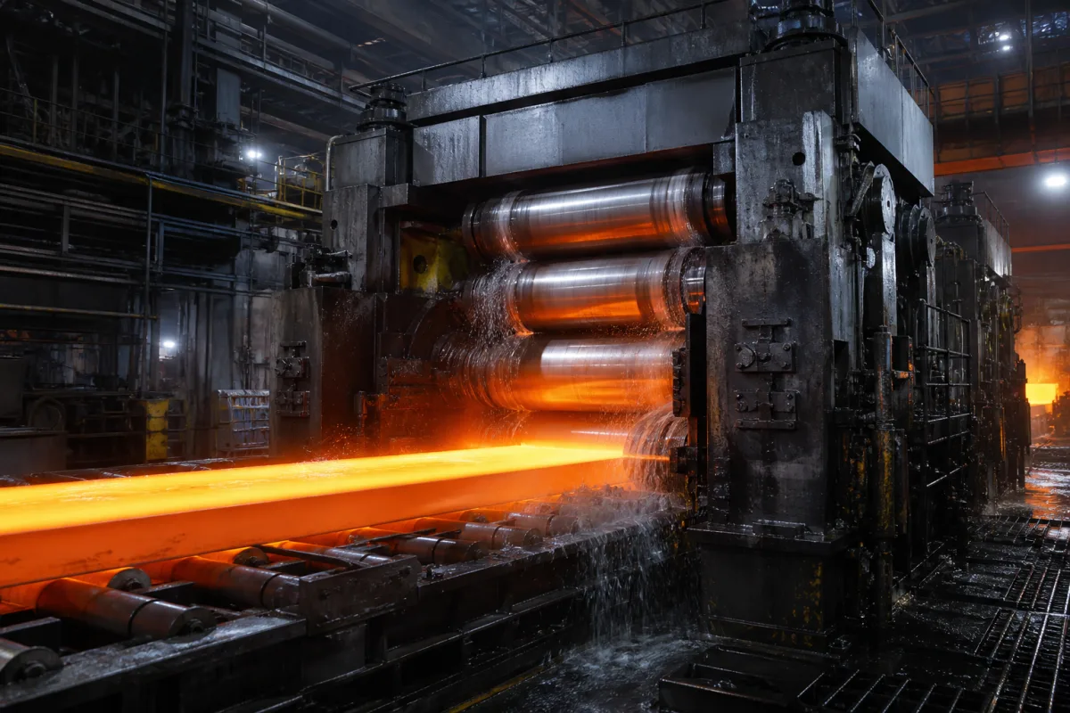
Rolling mill stands for hot strip and plate · Four-high stand build, roll sizes, longitudinal (mill) stiffness from housing, chocks, rolls and hydraulic press-down, gap and wear effects on stiffness and levelling, and component maintenance intervals
A heavy-duty rolling mill stand is the load-carrying unit of a rolling mill: two housings (frames) holding the work and backup rolls in bearing chocks, a screw or hydraulic press-down that sets the roll gap, and roll-change, bending and balance systems, arranged singly as a roughing or plate stand or in series as a multi-stand finishing train. Ask three things first: what product width, thickness range and rolling force the stand must take, what longitudinal stiffness and gap-control accuracy it delivers, and how wear of chocks, pads and rolls will be measured and maintained.
Two-high and four-high rolling mill stands for hot strip, plate and similar flat products, as roughing stands or in multi-stand finishing trains, including housings, roll stack, chocks and press-down. Work rolls (see heavy duty rolling mill work roll), mill housings sold alone (see mill housing), hydraulic gap control systems (see heavy duty rolling mill hydraulic gap control system) and complete hot strip lines are outside this page except where integrated.
CNFX editorial research · Sources checked October 11, 2026 · 4 sources
Kong and co-authors (Processes, 2026, University of Science and Technology Beijing with Guangxi BG and Aston University) modelled a 1,580 mm four-high hot strip finishing stand with 1,550 mm diameter backup rolls (1,400 mm necks, 1,715 mm between bearings) and 700 mm diameter work rolls (625 mm necks, 1,780 mm long), loading it from 3,000 to 15,000 kN. They treat the hydraulic cylinder, top and bottom backup-roll chocks, roll system and housing as springs in series and parallel. [1]
The structural stiffness of each side excluding the hydraulic system was 5,018 kN/mm and the hydraulic press-down 7,203 kN/mm, giving 2,957 kN/mm per side and 5,915 kN/mm for the mill in the model; production tests on the 1,580 mm finishing mill measured 2,678 and 2,683 kN/mm per side and 5,361 kN/mm total, a difference under 10%. The authors note that mill stiffness is measured during backup-roll changes or shutdowns by controlled press-down loading. [1]
Editorial calculation: with a mill stiffness of 5,361 kN/mm, a 1,000 kN rise in rolling force opens the loaded roll gap by about 1,000 / 5,361 ≈ 0.19 mm unless the gap control compensates; ask the supplier for the stand stiffness and the gap-control response that keep thickness within your tolerance. [1]
Give the supplier the product (strip, plate; steel grades), width and thickness range, maximum rolling force and torque, stand type (two-high, four-high; roughing or finishing), roll diameters and barrel lengths, required mill stiffness, press-down type and stroke, roll bending and shifting, roll-change system, drive power and speed, foundation interface and maintenance access.
02
Plan for wear, gaps, levelling and maintenance
The study lists maintenance intervals for finishing-mill components of 1–2 years for frame maintenance and step pads, 2 years for bearing chocks, 1–2 years for F1–F4 work rolls and 3 months for F5–F7 work rolls. It found that work-roll horizontal offset changes stiffness non-linearly, that work-roll rotation and roll crossing reduce stiffness and increase side-to-side asymmetry, and that one-sided vertical clearance from step-pad wear changes both total stiffness and asymmetry non-linearly. [1]
Asymmetric profile defects such as camber, wedge and off-centre running still depend on roll-gap levelling, and plant data showed a strong link between levelling variation and hydraulic-cylinder stroke difference under the same work-roll and step-pad condition, weakening after step-pad replacement. The authors applied the stiffness model to the stiffness-prediction module of a 1,700 mm hot strip mill. [1]
Editorial note: ask the supplier which wear parts (step pads, liners, chocks) set the clearance, how clearances are measured at roll change, and whether stiffness tests and levelling records are part of the handover.
03
Scale up to heavy plate stands: force, deflection and roll size
A TU Wien Automation and Control Institute project on a four-high heavy plate mill reports that the reversing stand is loaded with forces up to 90 MN, causing elastic deformation of up to 13 mm, made up of mill stand deformation, roll bending and roll compression, while plate thickness tolerances of 0.1 mm have to be met. Because exit thickness cannot be measured reliably close to the roll gap, it is calculated with a model that includes the compliance of the hydraulic and mechanical components and roll bending; the backup rolls reduce work-roll bending, and hydraulic bending systems or CVC rolls compensate it. [2]
SMS group's description of the 4.3 m heavy plate mill it supplied to TISCO lists the values in the table, with an annual capacity of 700,000 t (300,000 t stainless and 400,000 t carbon steel), co-axial CVC plus work-roll shifting, hydraulic roll adjustment and work-roll bending, and balancing forces of work and backup rolls that do not act on each other. [3]
Editorial calculation: 90 MN over 13 mm is about 90,000 / 13 ≈ 6,900 kN/mm of total stand-and-roll compliance, in the same order as the 5,361 kN/mm measured on the 1,580 mm strip stand above; meeting a 0.1 mm tolerance means compensating to within 0.1 / 13 ≈ 0.8% of that deflection. 109 MN over a 4.3 m barrel is about 25 MN per metre of barrel. [2][3][1]
A second builder's reference gives a comparison point. Primetals Technologies lists the equipment data for the 5 m plate mill it engineered for Dongkuk Steel's Dangjin Works as a maximum rolling force of 124,000 kN, main drive motor power of 2 × 10,000 kW, roll bending force of ±2,500 kN per side and rolling speed of 0 to 7.22 m/s. The finished plate range is 4.5 to 150 mm thick, 900 to 4,800 mm wide and 3 to 25 m long, for a design output of 1.5 million tonnes a year; the finishing stand carries SmartCrown® profile control and long-stroke AGC. [4]
Editorial calculation: 124 MN is about 14% above the 109 MN of the 4.3 m SMS group stand (124 / 109 ≈ 1.14), while both quote a top rolling speed near 7 m/s (7.22 and 7 m/s); the 20 MW of installed drive power and the ±2,500 kN bending force per side are values to ask any supplier to state for your own width and force. [4][3]
Published heavy plate stand
Value
Rolling force
109 MN
Work rolls
1,150 × 4,600 mm
Backup rolls
2,300 × 4,300 mm
Maximum rolling speed
7 m/s
Maximum entry thickness
960 mm
Plate width / length
1,550–4,200 mm / 6,000–38,000 mm
Vertical edger
1,000 mm rolls, 7,000 kN, 2 × 260 kNm
State the maximum rolling force and torque, roll dimensions with max and min diameters, entry thickness and roll-gap opening, product width and length, rolling speed, profile actuators (bending, shifting) and the thickness tolerance the stand and its model must hold.
04
Find rolling mill stand manufacturers
SMS group supplied the 4.3 m TISCO plate mill and Primetals Technologies engineered the 5 m Dangjin plate mill cited above; ask any stand builder for stiffness test records and references at a similar rolling force. [3][4]
05
Housings, backup and work rolls with chocks, hydraulic press-down, step pads and roll bending of a four-high stand
Mill width, roll diameters, rolling force, stiffness, maintenance intervals and drive power for a stand quotation
Published values in this table come from Kong et al.'s strip-mill study, TU Wien, SMS group and Primetals Technologies; where none states a value, the row says what to obtain from the supplier.
Explore company information and manufacturing capabilities, then discuss the scope of your project with a relevant supplier.
Share this page
Compiled and source-reviewed by the CNFX editorial team.
Each manufacturer above links to the page on that company's own website where the product is listed, with the date we checked it. How we source and review
· Page last updated 13 October 2026
Buyer questions
How stiff is a four-high hot strip finishing stand?
One 1,580 mm stand measured 5,361 kN/mm total longitudinal stiffness, against 5,915 kN/mm in a finite element model. [1]
Does wear change mill stiffness?
Yes; roll offset, roll crossing and step-pad wear changed total stiffness and side-to-side asymmetry in the study. [1]
How is mill stiffness measured in a plant?
During backup-roll changes or shutdowns, by applying controlled press-down loading and recording displacement. [1]
What rolling force do heavy plate mill stands take?
Published examples cite forces up to 90 MN with up to 13 mm elastic deformation, and a 4.3 m four-high stand rated at 109 MN. [2][3]
Why does a plate mill need a deflection model?
Deformation of up to 13 mm must be compensated to hold 0.1 mm thickness tolerances, and exit thickness cannot be measured reliably at the roll gap. [2]
How large is the rolling force of a wide heavy plate stand?
Primetals Technologies lists 124,000 kN maximum rolling force for the 5 m plate mill at Dongkuk Steel, and SMS group lists 109 MN for a 4.3 m plate mill at TISCO. [4][3]
Sources and what still needs a direct check
Sources checked 2026-10-11. The Processes study reports one four-high finishing stand; values for other stands depend on their size and design. Stiffness and force ratings for your stand must come from the supplier's design data and acceptance tests. The SMS group and Primetals Technologies reference pages give each builder's published data for one heavy plate stand.