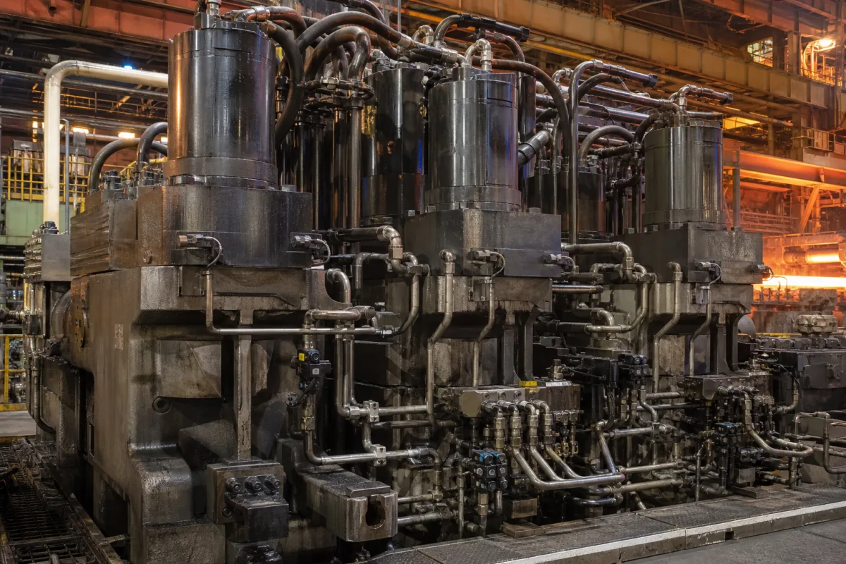
Hydraulic screwdown cylinder of a rolling mill: the ram, its oil column and how that oil is metered to set the roll gap
The screwdown cylinder and the oil it holds · how much oil moves the ram one micrometre, why the oil column is kept short while the stand still opens wide, metering that oil with a servo-motor booster instead of a servo valve, and cylinder size on large mills
In a hydraulic screwdown the roll gap is set by a ram pushed out of a cylinder on the mill housing, and what sits between the pump and the roll is a column of oil. That oil sets three things the screwdown can do: how many cubic millimetres must be pushed in to move the ram one micrometre, how far the ram springs back under a jump in roll force, and how wide the stand can be opened without making the column long. The cylinder, its stroke and the device that meters oil into it are the product here; the control loops that command it are a separate subject.
Hydraulic screwdown cylinders and their oil-metering hardware on rolling mills and roll presses: rams and cylinders mounted on the housing, stroke and oil-column height, separate lifting or mechanical pre-positioning used to open the stand, pilot-operated check valves and accumulators in the screwdown circuit, servo-motor-driven booster cylinders used instead of servo valves on small mills, and cylinder-mounted manifolds and valves on large mills. Level 1 gap control modes, position and force loops, side-to-side control and servo-valve response are covered on the Heavy-duty rolling mill hydraulic gap control system page; electromechanical screws, worm gears and the conversion of screw mills to hydraulic cylinders on the Electromechanical screwdown mechanism page; position transducers on gap cylinders on the Position transducer for rolling mill hydraulic cylinders page; the stand frame on the Rolling mill housing page; servo cylinders for casting-mould oscillation on the Servo actuator unit for continuous casting mould oscillation page.
CNFX editorial research · Sources checked October 12, 2026 · 4 sources
Oil per micrometre: a 180 mm ram at 2,000 N/cm² takes 25.4 mm³ for each µm of travel
Oono-Roll's US patent 10,562,086 (granted 2020) works through the numbers for a small mill. To produce a roll force of 100 tonnes with two screwdown cylinders whose rams are 180 mm in diameter, the oil chamber must be at 2,000 N/cm²; to raise the ram by 1 µm at that force, 25.4 mm³ of high-pressure oil must be added to the chamber. [1]
Editorial calculation: a 180 mm ram has an area of π × (90 mm)² ≈ 25,450 mm² (254.5 cm²), so 50 tonnes per cylinder (about 490 kN) gives roughly 1,930 N/cm², in line with the patent's 2,000 N/cm² (20 MPa); and 25,450 mm² × 0.001 mm is 25.4 mm³, the patent's figure. Thickness control in micrometres is therefore control of tens of cubic millimetres of oil per step on a ram of this size. [1]
The patent places the 1,000-tonne-plus tandem mills of large steelmakers on hydraulic screwdowns built from a hydraulic servo control valve and a hydraulic jack, and sets its own device for small mills and roll presses of 500 tonnes roll force or less. [1] In its circuit, a pilot-operated check valve stops oil returning from the rod-side chamber to the tank when the pump is off, and an accumulator holds pressure on the opposite chamber so the ram does not drop under its own weight when there is no roll force. [1]
Ask for ram diameter, maximum pressure, the oil volume under the ram at your thinnest and thickest gauge, and how the ram is held when the pump stops.
02
Keeping the oil column short while the stand still opens wide: a separate lift and a fixed roll-force piston
Sundwiger Eisenhütte's US patent 5,142,896 (priority 1989) describes the conflict on a cluster mill whose upper part is guided on four columns, each with a hydraulic screw-down unit. If one double-acting piston both raises the upper part and applies the roll force, its maximum stroke must cover the whole thickness range of the stock; with thin stock the oil-filled cylinder space is then tall, and because of its volume the upper part yields resiliently under high roll forces. [2]
A short cylinder space, on the other hand, limits the thickness range and the opening available for threading strip, clearing scrap after a break and changing rolls. The patent separates the two jobs: a lifting device on each column, hydraulic or mechanical and independent of the screw-down, opens the stand wide, while the roll-force piston is fixed to the column at a set position so that only a short oil space carries the roll force. [2]
It gives two ways of fixing that piston: on a spindle screwed into the column and turned by an adjusting motor, which positions it steplessly, or as a double-acting piston held against a stop on the column with spacing elements inserted for different roll gaps. [2] A related arrangement on a large plate mill keeps electromechanical screw-down gears and adds hydraulic cylinders to support them, as in Danieli's 2020 upgrade of Marcegaglia's four-high plate mill at San Giorgio di Nogaro, Italy, reported by AIST together with new gauge control and a Level 2 pass-schedule model. [4]
How the stand is opened
How roll force is applied
Source
Same double-acting piston
Same piston; stroke covers the full thickness range, so the oil space grows for thin stock
Ask for the hydraulic stroke, the gap opening available for threading and roll change, and how that opening is produced if the roll-force stroke is short.
03
Metering the oil without a servo valve: an AC servomotor, ball screw and 20 mm booster piston on a small mill
Oono-Roll's device moves the ram quickly with ordinary pump oil through a solenoid valve, then closes the pilot check valve so that the oil between the screwdown cylinder and a booster cylinder is trapped. A control motor turns a screw that drives the booster piston, pushing a set quantity of oil into the screwdown cylinder or drawing it back, so that the ram moves in micrometres; the patent states that the solenoid-valve stage alone cannot stop the ram finely in microns. [1]
The control motor is an AC servomotor that can reverse at high speed, and the screw is a ball screw chosen to minimise backlash. The control panel sets the motor angle from an external reference, the position sensor on the screwdown cylinder and the load cell under the lower roll chock, so the same mechanism can hold position or roll force. [1]
Editorial calculation: the 20 mm booster piston has an area of about 314 mm², about 1/81 of the 180 mm ram, so 0.081 mm of booster travel delivers the 25.4 mm³ needed for 1 µm of ram travel, matching the patent; holding 2,000 N/cm² on that small piston takes about 6.3 kN of screw force instead of the 490 kN on the ram. [1]
For a small mill or roll press, ask whether a servo valve or a servo-motor booster meters the oil, the booster stroke and resolution, and how pressure is held when the motor is idle.
04
Cylinders on large mills: bores up to 2,000 mm, the manifold on the cylinder and a reserve valve
Bosch Rexroth's technical information RE 08177 (edition 2025-03) states that its gap-control cylinders are built from high-strength forged parts and available in diameters up to 2,000 mm. The valve manifold is mounted directly on the cylinder or piped close to it for maximum hydraulic stiffness; servo valves or 3WRCE-4X servo-solenoid piloted proportional valves control position and flow, with partial redundancy so a reserve valve takes over on a fault, and covers with positive-pressure purging keep vapour and dirt off the valves. Position sensors are contactless and mounted inside the cylinders. [3]
For retrofits the same document lists raising system pressure and flow, changing to less flammable or environmentally friendly fluids and adding functional safety, and proposes decentralised drives built near or into the actuator where the existing power unit limits performance. Its gap-control simulation model uses a 280 bar supply and a servo valve characterised at 180 Hz; these are model parameters, not a product rating. [3]
Editorial calculation, as an order of magnitude only: a 2,000 mm bore has an area of about 3.14 m², which at the 280 bar (28 MPa) of Rexroth's model would develop about 88 MN; at the 25.4 mm³-per-µm logic of the small-mill example, the same bore would take about 3,140 mm³ of oil per micrometre. Actual force ratings and oil volumes depend on bore, pressure rating and column height and must come from the supplier. [3][1]
Ask for bore, rod and pressure rating with the resulting force, the oil-column height, where the manifold and valves sit, the redundancy concept and the sensor mounting.
05
Mill, force and oil-column data for a hydraulic screwdown cylinder
Paste it into your enquiry below or into an email to a maker, then replace every bracket.
Mill: [two-high, four-high, cluster; strip, plate or roll press; maximum roll force]
Cylinders: [number per stand; ram or bore diameter; maximum pressure]
Stroke: [roll-force stroke; gap opening for threading and roll change; separate lift or mechanical pre-positioning]
Oil column: [height at thinnest and thickest gauge]
Metering: [servo valve, proportional valve or servo-motor booster]
Holding: [pilot check valve; accumulator on the opposite chamber]
Measurement: [position sensor on the cylinder; load cell]
Supply: [pressure; fluid; existing power unit or decentralised drive]
Explore company information and manufacturing capabilities, then discuss the scope of your project with a relevant supplier.
Share this page
Compiled and source-reviewed by the CNFX editorial team.
Each manufacturer above links to the page on that company's own website where the product is listed, with the date we checked it. How we source and review
· Page last updated 13 October 2026
Buyer questions
How much oil moves a screwdown ram one micrometre?
In Oono-Roll's worked example, a 180 mm ram at 2,000 N/cm² needs 25.4 mm³ of oil per micrometre of travel, for 100 tonnes of roll force shared by two cylinders. [1]
Why keep a hydraulic screwdown's oil column short?
Sundwiger Eisenhütte's patent explains that a tall oil-filled cylinder space lets the upper part yield resiliently under high roll force, so it opens the stand with a separate lift and keeps the roll-force oil space short. [2]
Can a hydraulic screwdown work without a servo valve?
Oono-Roll's device for mills of 500 tonnes or less meters oil with a booster piston driven by an AC servomotor and ball screw, after a pilot check valve traps the oil. [1]
How large are hydraulic gap-control cylinders on big mills?
Bosch Rexroth states that its gap-control cylinders are available up to 2,000 mm in diameter, with the valve manifold on or close to the cylinder. [3]
Sources and what still needs a direct check
Sources checked 2026-10-12. Two US patents from mill builders give the hardware arrangements and numbers: Oono-Roll (granted 2020) for small mills and roll presses, Sundwiger Eisenhütte (granted 1992) for cluster mills. Bosch Rexroth's 2025 technical information covers large-mill cylinders and valves, and an AIST news item reports a plate mill upgrade by Danieli.