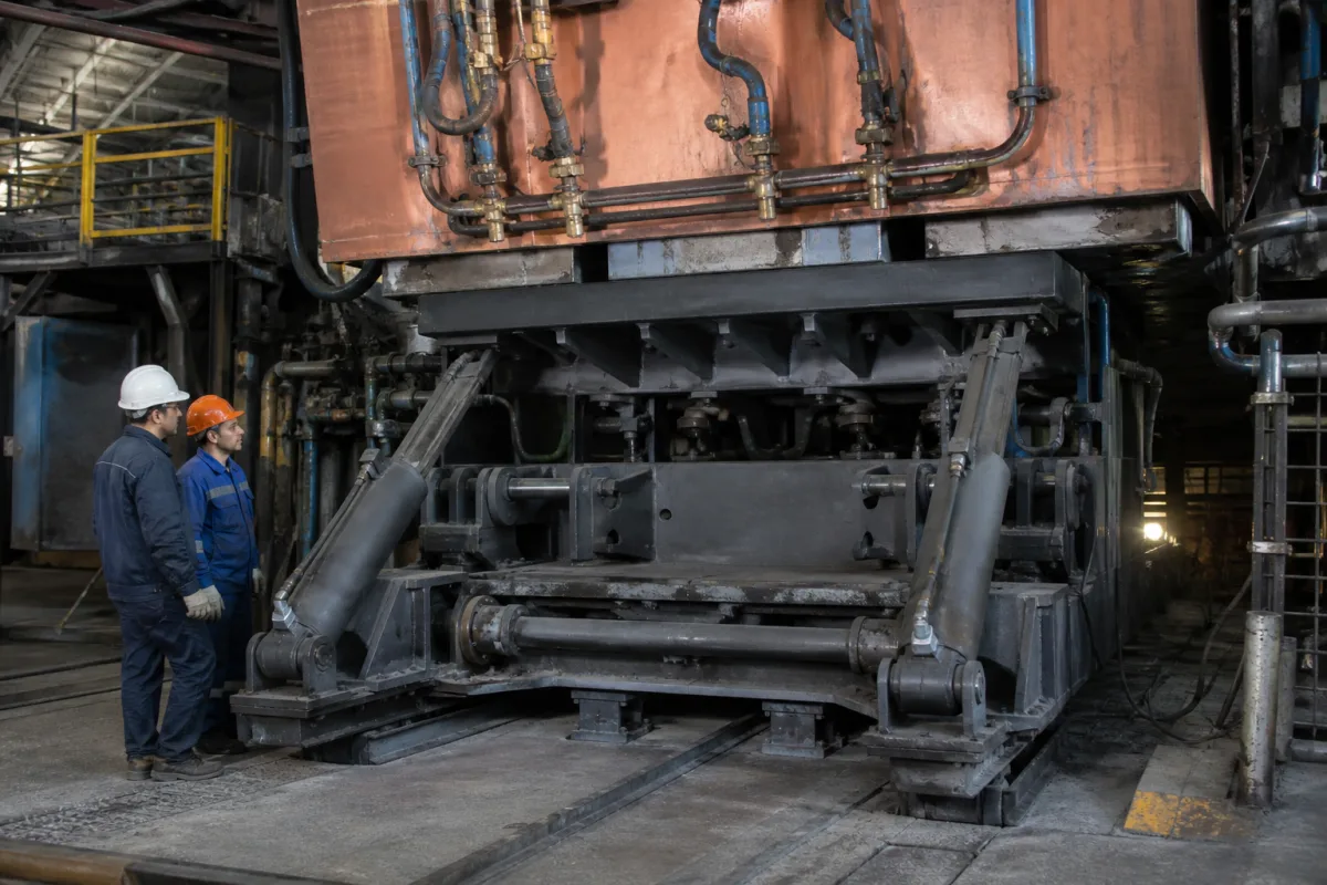
Servo actuator unit for continuous casting mould oscillation: hydraulic servo cylinders and electric ball-screw drives that replace the eccentric
The servo actuator that drives a caster's mould table · hydraulic servo cylinders against electric ball-screw actuators, how the cylinders are mounted, one position transducer per drive, and what wears in a ball screw that only turns a few degrees
A mould oscillator can be driven by a motor and eccentric, but servo-driven units swap that eccentric for an actuator that can change its motion while the caster runs. Two kinds are in use: a hydraulic servo cylinder fed through servo valves, or an electric servo motor turning a ball screw. Choosing between them, and specifying either, comes down to a few hardware questions: what the actuator lets the operator change during casting, what it needs in maintenance, how it is fixed to the frame so that the table's small sideways movements do not break it, and how two or more actuators under one table are kept moving together.
Servo actuator units that drive the oscillation of continuous casting moulds: hydraulic servo cylinders with their servo valves, mounting and joints, electric servo actuators with servo motor, belt drive, vertical ball screw, ball splines and lubrication, and the per-drive displacement transducers and comparing circuits that close each actuator's position loop. The choice of stroke, frequency and waveform, negative strip time, oscillation control software and oscillation measurement are covered on the Heavy-duty continuous casting mold oscillator page; four-eccentric and lever-linkage oscillators with their guide rods, leaf springs and anti-roll bars on the Continuous casting mould oscillation mechanism page; strand guide segments below the mould on the Strand guide system for continuous casters page; mould copper plates on the Continuous casting mold copper plate page. Servo-hydraulic injection units of plastics moulding machines, which are a different application, are covered on the Injection drive and control system for plastics injection moulding machines page.
CNFX editorial research · Sources checked October 12, 2026 · 4 sources
Hydraulic servo cylinder or electric ball-screw actuator in place of the eccentric cam
Two US patents granted to JP Steel Plantech in 2019 set the three drive types side by side. In the eccentric-cam oscillator a motor on the floor turns an eccentric cam, and a link from the cam swings the main arm of a parallel linkage that carries the oscillation table and mould. The hydraulic servo-type oscillator installs a hydraulic servo cylinder in place of the cam, its piston pinned to the end of the main arm; the electrically driven servo-type installs an electric servo actuator there instead. [1]
According to the patents, the eccentric-cam oscillator cannot change its amplitude during casting and its waveform is limited to a sine. The hydraulic servo cylinder can change amplitude during casting, by adjusting when the advancing and retracting pressures are applied to the piston, and can run a non-sinusoidal waveform; the price is inspection of filters and hydraulic oil and control of oil contamination. The electric servo actuator can also change amplitude during casting and run either a sinusoidal or a non-sinusoidal waveform. [1][2]
In the electric actuator described, a servo motor mounted with its shaft pointing down drives a pulley, and a belt turns a second pulley on the lower end of a vertical ball-screw shaft carried in angular bearings. The ball nut rides on the screw, a nut-side shaft fixed to it is guided by ball splines in a cylinder tube, and its upper end is pinned to the main arm. [1]
A 1987 Mannesmann patent had already named both options for a multi-drive table: hydraulic cylinder and piston drives controlled through servo valves, or electrical linear drives whose power current is controlled through amplifiers and switches by the same comparing circuit. It also states that the drives should be connected to an energy source giving a force considerably larger than the maximum friction between strand and mould plus any friction in the table. [4]
Screw and nut wear under small-angle reversing motion [1][2]
Ask which actuator is offered, the force it delivers against the strand friction and table friction expected on your caster, and the maintenance it needs: oil cleanliness and filter checks for a servo cylinder, lubrication and screw repositioning for a ball-screw unit.
02
Fixing the servo cylinders to the frame: an elastic bending web under each cylinder instead of a spring-necked piston rod
A 1998 US patent from SMS Schloemann-Siemag deals with servo hydraulic cylinders that oscillate a slab mould guided on a support frame. It criticises an earlier German design in which the cylinders sat on the sides of the frame and the ends of the piston rods were necked down into spring elements to absorb tangential movement: those reduced sections carry high tensile, compressive and buckling stresses and can fail in fatigue. [3]
The patent's solution fixes each cylinder's base plate rigidly on a fastening element anchored to the support frame. That element is an elastic web of reduced cross-section with a fastening flange at each end; the piston rod is connected through a joint to the mould table, which itself rides on parallel guide members pivoted on bearing posts. When the table moves sideways the whole cylinder pivots on the elastic web instead of bending the piston rod, and the longer lever reduces the bending and buckling stresses. The stated aim is a drive that runs without play while compensating for mounting inaccuracy, thermal expansion and tangential movement. [3]
The arrangement in the image on this page, inclined cylinders under a table carrying a copper-faced mould, is a general illustration; the patent drawing places the cylinders under the mould table beside parallel guide members. [3]
Ask how each cylinder is fixed to the frame and to the table (elastic element, trunnion or clevis, joint type), how mounting errors and thermal growth of the frame are absorbed, and what the piston rod sees in side load.
03
Three drives, three transducers: keeping a servo-driven table from skewing
Mannesmann's US patent 4,703,789 (priority 1985) addresses a table driven by a plurality of drive elements and sets out to stop the mould from skewing relative to the strand. It places a displacement transducer along the path of each drive, compares each signal with reference values that describe the intended oscillation, and uses any deviation to correct that drive. [4]
In the preferred arrangement there are three drives and three load-relief springs, with three transducers tracking the drives; the reference source sets the contour, amplitude and rate of the desired oscillation. With the position of each drive known, the patent notes, the position of any point of the mould can be tracked. [4]
For a hydraulic drive it separates a power part, the cylinder, from a control part, one or more servo valves fed from the same pressure source and driven by the comparing circuit. The oscillating table is to be mounted on springs, preferably hydraulically adjusted oil springs, with different spring constants, particularly for a curved caster, and a hydrostatic wedge bearing may guide the table; ball bearings are mentioned as an option when lifting strokes are small. [4]
Ask how many actuators carry the table, where each position transducer sits, whether each actuator has its own closed loop, and how load-relief springs share the mould weight.
04
Keeping a ball-screw actuator alive when it only turns a few degrees each way
JP Steel Plantech explains the weak point of the electric actuator: the amplitude needed for mould oscillation is small, about ±6 mm in its example, so the threaded shaft turns back and forth through a small angle during long continuous operation, and under ordinary grease lubrication the oil film can break down. [1] Editorial calculation: ±6 mm is a total travel of 12 mm per cycle at the actuator's output, before any lever ratio of the arm. [1]
Its first patent (US 10,189,078) encloses the screw in a casing that keeps the ball nut and the engaged part of the threaded shaft submerged in an oil bath. Oil drains from a lower outlet to a lubricating-oil tank and is pumped back through an inlet above the outlet; a bearing retainer with a shaft seal stops oil leaking down, and a rotating and a stationary parasol-shaped shield below it catch oil and lead it to a drain. [1]
Its second patent (US 10,232,432) attacks wear at the point where screw and nut keep reversing about the same mean position. The actuator's foundation is made adjustable, by inserting liners under it or by a hydraulic or screw jack, so that with the oscillator stopped the relative height of the bearing and the nut-side shaft can be changed and the screw-fitting position shifted. Periodically moving that position spreads the wear and, the patent states, lengthens actuator life. [2]
Wear point in the electric actuator
Measure in JP Steel Plantech's patents
Ball nut and screw under small-angle reversing
Oil bath in a casing with circulation through a tank [1]
Oil escaping along the rotating shaft
Bearing retainer with shaft seal; rotating and stationary parasol shields to a drain [1]
Wear concentrated at one screw-fitting position
Foundation height changed by liners or a hydraulic or screw jack to shift the mean position [2]
For an electric actuator, ask for the lubrication method of screw and nut, the expected service life at your stroke and frequency, and whether the screw's mean working position can be shifted without dismantling.
05
Caster and actuator data for a mould oscillation servo unit
Paste it into your enquiry below or into an email to a maker, then replace every bracket.
Caster: [slab, bloom or billet; straight or curved mould; mould and table mass]
Motion: [stroke range; frequency range; non-sinusoidal waveform needed]
Actuator: [hydraulic servo cylinder or electric servo ball screw; number of actuators]
Force: [maximum strand friction expected; table friction; load-relief springs]
Mounting: [base fixing; rod or shaft joint; allowance for thermal growth]
Control: [position transducer per actuator; servo valve or drive amplifier; reference signal source]
Hydraulics (if used): [pressure; oil cleanliness target; filtration]
Electric (if used): [servo motor rating; screw lubrication; repositioning of screw mean position]
Explore company information and manufacturing capabilities, then discuss the scope of your project with a relevant supplier.
Share this page
Compiled and source-reviewed by the CNFX editorial team.
Each manufacturer above links to the page on that company's own website where the product is listed, with the date we checked it. How we source and review
· Page last updated 13 October 2026
Buyer questions
What is the difference between a hydraulic and an electric servo mould oscillator?
JP Steel Plantech's patents state both can change amplitude during casting and run non-sinusoidal waveforms; the hydraulic servo cylinder needs filter and oil inspection and contamination control, while the electric ball-screw actuator faces wear from small-angle reversing motion. [1]
How are servo cylinders mounted under a mould table?
An SMS patent fixes each cylinder's base on an elastic bending web with flanges, so the cylinder pivots when the table moves sideways instead of bending a necked piston rod. [3]
How is a multi-cylinder oscillation table kept level?
Mannesmann's patent gives each of the three drives its own displacement transducer, compares each with a reference oscillation and corrects each drive through its servo valve. [4]
Why does a ball-screw mould oscillator wear?
The screw turns through a small angle about the same position for long periods, about ±6 mm of amplitude in JP Steel Plantech's example; the patents answer with an oil bath and with liners that shift the screw's working position. [1][2]
Sources and what still needs a direct check
Sources checked 2026-10-12. Four US patents from three companies: two from JP Steel Plantech (granted 2019, priority 2015) on the electric ball-screw actuator, one from SMS Schloemann-Siemag (1998) on mounting servo hydraulic cylinders, and one from Mannesmann (1987) on per-drive position control of a multi-drive table.