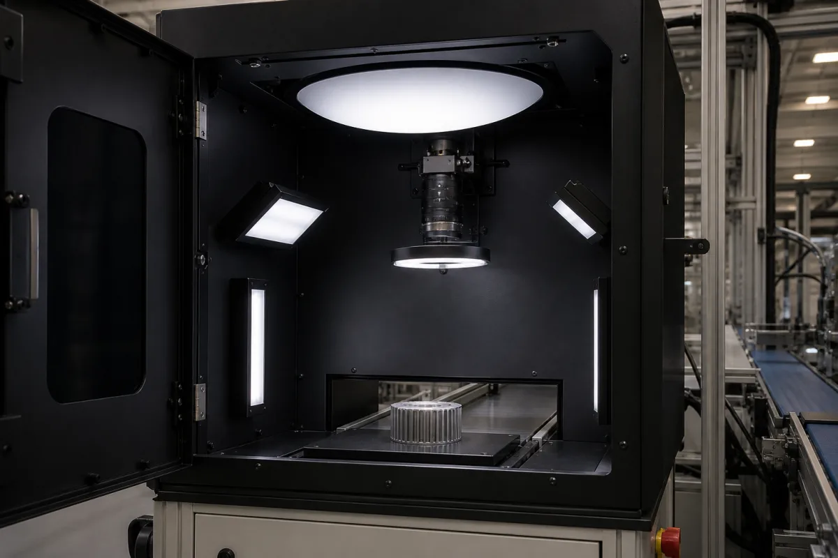
Controlled lighting chamber for in-line vision inspection: a light-tight cabinet around the camera and lights, and the ambient-light choices it competes with
The dark cabinet that closes round a vision camera and its lights on the line · when shutting out ambient light is the right answer, what a bandpass filter or an overdriven strobe does instead, and how stable the light inside has to stay
A vision inspection station on an open line sees two kinds of light: the light its own LEDs put on the part, and whatever else reaches the part — overhead lighting, daylight, a reflective jacket on the operator walking past. A controlled lighting chamber is the cabinet that settles the question physically. The camera, its lights and the inspection position sit inside a dark, matt enclosure with an opening for the conveyor and a door for setting up, so the only light in the image is the light the system controls. Shrouding is not the only way to beat ambient light, though, and it has costs of its own, so the chamber is best specified alongside the alternatives and together with the control of the lights inside it.
Enclosed, light-tight inspection cabinets and shrouds for machine vision stations on production lines — housing, door and conveyor openings, matt interior, mounts for camera and dome, ring or bar lights — and the choice between shrouding, optical filtering and strobing to control ambient light. The lights and controllers themselves are covered on the Machine vision illumination unit page and the LED lighting system for machine vision (ring, bar and dome lights with strobe control) page, angled bar arrays on the LED illumination array for machine vision page, booths for human visual inspection on the Inspection lighting system for human visual inspection workstations page, and complete camera-and-software inspection systems on the Machine vision system for inspection page. Photostability and plant-growth light chambers are outside this page.
CNFX editorial research · Sources checked October 12, 2026 · 4 sources
Cabinet, bandpass filter or overdriven strobe: three ways to keep factory light out of the image
Alan Lockard, writing in Vision Systems Design from years of designing vision inspections, sets the requirement: a system on the plant floor should show no effects of ambient light, and an inspection that changes when an operator stands between the overhead lights and the part has a problem. Shrouding the inspection area is one way to block ambient light, but he notes that it also blocks visual inspection of the object, and in pharmaceutical and other quality-critical plants shrouded line sections complicate line-clearance procedures. [1]
The filter route has its own specification work. MidOpt's tolerance on centre wavelength is ±10 nm for its BP and BN series and ±3 nm for its Bi interference filters, with peak transmission above 85% for every listed part except the deep-UV BP250 (above 40%); it designs the broad series to allow for wide-angle lenses and for variation in LED output. [2] Lockard adds that a matching bandpass filter limits ambient influence to that band only, so ambient light inside the band still reaches the sensor. [1]
For the strobe route, Gardasoft gives the example that overdriving an LED by 200% doubles its intensity, lets the exposure be halved and, in its words, reduces the effects of ambient light by a factor of 4. [3] Editorial calculation: if the LED light collected per frame is held equal (twice the intensity for half the time), the ambient light collected in the halved exposure falls by half, so the ratio of ambient to LED light in the image improves by a factor of 2 on this simple reading; ask the supplier how its figure is derived before relying on either number.
Lockard's check works for all three: unplug the LED lights and trigger an inspection; if the image is completely dark, ambient light is very unlikely to affect the inspection. [1] Editorial note: run it with the cabinet door shut and open, and at the brightest time of day.
Approach
How it works against ambient light
Published figures and cautions
Light-tight cabinet or shroud
Blocks ambient light physically around camera, lights and part
Hides the part from operators; affects line clearance in pharma [1]
Bandpass filter on the lens, matched to monochrome LEDs
Passes only the LED band; ambient light outside it is blocked
MidOpt says it removes the need for shrouding; BP series 65–315 nm wide, BN series 45–55 nm for overwhelming ambient light, Bi series 28 nm [2]
Overdriven strobe with short exposure
LED pulse far brighter than its continuous rating, so ambient light contributes less to each frame
Up to 10× rated brightness in short pulses [3]; 1 ms at 500% with 250 µs exposure in one installation [1]
Editorial note: a cabinet is the robust answer when the inspection uses more than one colour or a broad white light that a single bandpass filter cannot isolate, or when strobing cannot be raised further; it is the wrong answer where operators must see the product or where line clearance requires open guarding.
02
Light that stays the same inside the cabinet: LED temperature, drive current and measurement drift
Shutting out ambient light only removes one source of variation; the lights inside the chamber vary too. Lockard notes that LED brightness can drop by as much as 40% as the LEDs heat from 25 °C to 90 °C, and that applications with image contrast below 20% are sensitive to even slight changes in LED output. [1] Gardasoft states that, even for simple calliper measurements, a 10% change in light level can change the measured value by 0.5%, and that LED brightness depends on the drive current rather than the supply voltage. [4]
Editorial calculation: on Gardasoft's ratio, the full 40% fall Lockard describes would shift a calliper reading by about 2% if nothing compensated for it (0.5% per 10% of light, scaled linearly), which is why the lights in an enclosed station should run from a current-regulating controller rather than a fixed voltage supply. This is a linear extrapolation, not a figure from either source.
Heat matters more inside a closed cabinet than on an open frame. Gardasoft notes that pulsing the light only when an image is taken minimises the heat produced, and that an LED lit for 10% of the time has its lifetime increased by a factor of 10. [3] Editorial note: ask the supplier for the cabinet's internal temperature with all lights at their working setting and the door shut, and for the light output measured at that temperature.
03
What the cabinet itself has to provide
With the light sources chosen, the enclosure's own job is mechanical and optical: hold the camera and lights in fixed positions, keep stray light out, and keep its own surfaces from reflecting the lights back into the image.
Editorial note: in a cabinet like the one pictured, with a dome overhead, a ring light at the lens and bar lights on the side walls, specify the conveyor opening height and width against the largest part with the smallest clearance that still passes it, a matt dark interior finish, adjustable mounts so each light's angle and height can be set and locked, a door seal against light leakage, and a door interlock if the lights are bright enough to dazzle an operator when it opens. Ask for the cabinet to be tested with Lockard's unplugged-light check at the installed position. [1]
04
What to send for an enclosed vision lighting station
Paste it into your enquiry below or into an email to a maker, then replace every bracket.
Part: [size; surface finish; colours; largest part through the opening]
Line: [conveyor width and speed; opening height and width; line-clearance rules]
Optics: [camera and lens; working distance; field of view]
Lights: [dome, ring, bar or back light; wavelength; continuous or strobed; overdrive level]
Ambient control: [cabinet, filter, strobe or a combination; bandpass filter part]
Stability: [light controller type; internal temperature at working settings]
Acceptance: [image with LEDs unplugged; repeatability on a reference part]
Explore company information and manufacturing capabilities, then discuss the scope of your project with a relevant supplier.
Share this page
Compiled and source-reviewed by the CNFX editorial team.
Each manufacturer above links to the page on that company's own website where the product is listed, with the date we checked it. How we source and review
· Page last updated 13 October 2026
Buyer questions
Do I need a light-tight cabinet for machine vision?
Not always. Lockard notes that shrouds block visual inspection and complicate pharma line clearance, while strobing and matched bandpass filters can reduce ambient influence; MidOpt says its filters remove the need for shrouding. [1][2]
How bright can an overdriven vision light run?
Gardasoft says overdrive can boost output up to 10× the brightness rating in short pulses. [3]
How much does LED light vary inside an inspection station?
Lockard reports drops of up to 40% as LEDs heat from 25 to 90 °C; Gardasoft says a 10% light change can shift a calliper measurement by 0.5%. [1][4]
How do I check that ambient light is not affecting the inspection?
Unplug the LED lights and trigger an inspection; if the image is completely dark, ambient light is very unlikely to have an effect. [1]
Sources and what still needs a direct check
Sources checked 2026-10-12. Ambient-light requirements, the shrouding trade-off, LED temperature drift and the unplugged-light check come from Alan Lockard's article in Vision Systems Design; filter series, bandwidths, tolerances and the claim that filters replace shrouding from MidOpt's bandpass filter specification sheet; overdrive, ambient-light reduction, lifetime and the light-to-measurement ratio from two Gardasoft application articles.