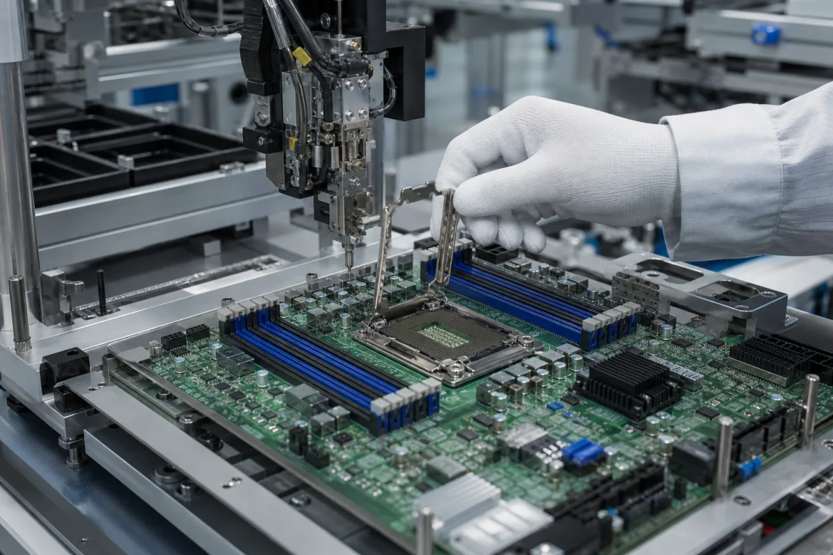
Server CPU socket assembly: LGA socket body, bolster and back plate, and the load that seats thousands of contacts
Server boards · the land grid array socket soldered under a server processor, with its bolster plate, back plate and loading hardware: reflow onto the board, the clamping load the contacts need, and the contact resistance and mating cycles it is built for
Under a server processor sits a land grid array socket: thousands of spring contacts in a plastic housing, soldered to the motherboard by balls, with a pick-and-place cap on top until the processor goes in. The socket alone does not make contact; a loading mechanism (a lever-operated load plate, or a bolster plate with screws) and a back plate under the board press the processor down, and the heat sink adds load. The picture shows a server board in an assembly fixture with the socket's load plate held open. Three things define the assembly: how the socket is soldered and inspected, the clamping load window, and the contact resistance and number of mating cycles it guarantees.
Production land grid array (LGA) processor sockets for server and workstation boards, with their pick-and-place cap, independent loading mechanism or bolster plate, back plate and heat sink load. The complete board is covered on the Motherboard page; test sockets and contactors used to test packaged chips are covered on the IC test socket (contactor) page.
CNFX editorial research · Sources checked October 12, 2026 · 3 sources
Soldering a 3,647-contact socket to the board: 1.6–2.4 mm FR-4, 0.1 mm bow per 25.4 mm, a 245 °C peak and X-ray inspection
TE Connectivity's application specification 114-115011 (Rev. A, 2016) for its LGA3647 server socket sets out what the board and reflow process must achieve. The socket's contacts sit on a hexagonal 0.8585 × 0.9906 mm pitch in two C-shaped regions, and it is used with a bolster plate assembly, a back plate assembly and a carrier. [1]
TE recommends no-clean flux (RMA type acceptable), says the socket must not be washed, and warns against storing sockets near ammonia, amines, nitrites, sulfur compounds and other chemicals listed that can cause stress corrosion cracking of the solder balls. [1]
Editorial calculation: 0.1 mm per 25.4 mm is a slope of about 0.39 %; across a socket grid about 76 mm long (an assumed length for illustration), the allowed bow is about 0.3 mm, which is in the same range as the 0.3–0.5 mm solder-ball stand-off TE specifies after reflow.
SAC paste (217 °C melting); peak 245 ±5 °C; 40–100 s target time above 217 °C as read from TE's profile figure; preheat 150–170 °C; at least 7–8 oven zones; under 15 °C across the socket area; 260 °C maximum at the cap [1]
Even melting across a large, heavy part
Placement
Up to 14.5 g per segment; handle by the outer perimeter only; do not touch contacts or balls [1]
Bent contacts and deformed balls
After reflow
Stand-off 0.3–0.5 mm; X-ray or electrical test to find shorts [1]
Hidden joints cannot be seen
Rework
Socket is not repairable or reusable once removed; peak body 260 °C; joints 228–250 °C for 45–280 s [1]
Rework means a new socket
Specify the socket type and pin count, board thickness and material, the warpage limit, the reflow profile and number of oven zones, the X-ray inspection criteria and the rework policy.
02
Clamping the processor onto its contacts: 613–1,333 N on the LGA3647 bolster stack against 311–822 N for a desktop LGA1155
The contacts need a minimum force to make electrical connection and a maximum the socket and board can take; the loading hardware and heat sink together must stay in that window for the life of the server.
Intel explains that its minimum is a beginning-of-life load, set to seat the processor electrically and allowing for load degradation over time, while the maximum must not be exceeded at any point in product life; the socket body must not be used as a mechanical reference or load-bearing surface for thermal solutions. [3] TE's LGA1156 socket hardware shows the parts of such a loading mechanism: a stainless-steel load plate and lever, a steel frame and screws, polypropylene insulators and a zinc- or nickel-plated steel back plate that stops the board bowing under compression, with a lever force of 49 N maximum. [2]
Editorial calculation: spread evenly, 613–1,333 N over 3,647 contacts is about 0.17–0.37 N per contact (17–37 gf), and 311–822 N over 1,155 contacts is about 0.27–0.71 N per contact.
Load
TE LGA3647 (server)
Intel LGA1155 with ILM (desktop, for comparison)
Total static compressive load
613 N (138 lbf) minimum to 1,333 N (300 lbf) maximum, from heat sink, bolster and back plate [1]
311 N (70 lbf) to 822 N (185 lbf), ILM plus heat sink [3]
Share from loading mechanism
Bolster and back plate assemblies with the heat sink [1]
Ask for the static load window at beginning and end of life, how much comes from the loading mechanism and how much from the heat sink, the back plate and bolster design, screw torque or lever force, and the maximum heat sink mass and shock level.
03
Contact resistance and mating cycles: 19 mΩ average and 100 mΩ maximum per contact, 15 insertions, and 30 durability cycles
The socket's electrical promise is stated per contact and at end of life, and the number of processor changes it survives is small.
TE's LGA1156 contacts are copper alloy with gold over nickel at the contact area, in a high-temperature UL94 V-0 thermoplastic housing, with 15 µin gold or gold-flash options, on a 0.914 × 0.914 mm grid. [2]
Editorial calculation: at the 19 mΩ average, a power path carried on 100 contacts in parallel has about 0.19 mΩ resistance; at 100 A that is 19 mV and about 1.9 W of heating in the contacts. Contact count and current per rail must come from the processor's own documentation; these numbers only show why the average and per-contact limits are both specified.
Requirement
Value
Source and basis
Average contact resistance
19 mΩ at end of life, averaged over 119 daisy chains [3]
Intel LGA1155; includes contact, solder ball and interface to the land
22 mΩ maximum average; 30 cycles; 0.45 mm nominal contact deflection [2]
TE LGA1156 socket, listed for desktops and low-end servers
Request the product specification and qualification test report for the exact socket (TE lists 108-115115 and 501-115139 for LGA3647), the contact resistance at end of life, durability cycles, contact plating thickness and the processor insertion limit.
04
Socket, board and loading details to specify
Paste it into your enquiry below or into an email to a maker, then replace every bracket.
Socket: [LGA type; pin count; pitch; contact plating]
Board: [material; thickness; warpage limit; land pattern]
Assembly: [stencil; reflow profile; X-ray criteria; rework policy]
Loading: [ILM or bolster; back plate; static load window; screw torque or lever force]
Thermal: [heat sink mass; its share of load; shock and vibration]
Electrical: [contact resistance average and maximum; inductance; insulation]
Life: [mating cycles; processor insertions]
Explore company information and manufacturing capabilities, then discuss the scope of your project with a relevant supplier.
Share this page
Compiled and source-reviewed by the CNFX editorial team.
Each manufacturer above links to the page on that company's own website where the product is listed, with the date we checked it. How we source and review
· Page last updated 13 October 2026
Buyer questions
How much force holds a server CPU in an LGA socket?
TE's LGA3647 application specification requires a total static compressive load of 613 N (138 lbf) to 1,333 N (300 lbf) from the heat sink, bolster and back plate. [1]
Can a server CPU socket be reworked?
TE states its LGA3647 socket is not repairable and must not be reused once removed from the board; a defective socket is discarded and replaced. [1]
What contact resistance does an LGA socket have?
Intel's LGA1155 guide sets 19 mΩ average and 100 mΩ maximum per contact at end of life; TE lists 22 mΩ maximum average for its LGA1156 socket. [3][2]
Sources and what still needs a direct check
Sources checked 2026-10-12. TE Connectivity is a socket maker publishing application and product data for its LGA sockets; Intel's thermal mechanical design guide sets socket and loading requirements for a desktop LGA1155 platform, used here for comparison and for its published electrical limits.