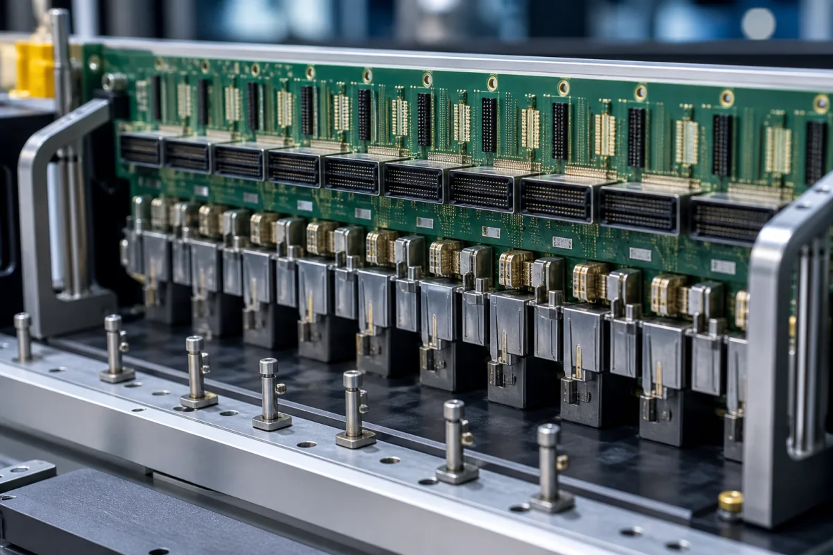
High-speed backplane and storage-backplane connectors for servers · data rate (Gb/s, NRZ and PAM4), differential impedance, pairs per column, press-fit mounting, mating force, mating cycles, PCIe, SAS and SATA support, SFF-8639 (U.2) drive connectors
A server backplane connector is the press-fit connector pair that joins a line card, compute sled or drive to the backplane or midplane of a server or storage chassis, carrying differential high-speed pairs, low-speed signals and power through one mating interface. Ask three things first: the data rate and signalling (NRZ or PAM4) and the impedance your channel is designed for; how many differential pairs you need and at what pitch; and how the connector is pressed into the board and how many mating cycles it must survive.
High-speed backplane, midplane and orthogonal board-to-board connector systems for servers, storage and networking equipment, and storage-backplane drive connectors to SFF-8639 (U.2) and SFF-8680 (SAS). The backplane printed circuit board itself (see multilayer PCB), motherboards, cable assemblies sold on their own and edge-card slot connectors are outside this page except where compared.
CNFX editorial research · Sources checked October 11, 2026 · 5 sources
Amphenol's ExaMAX datasheet describes a backplane connector system for 25 Gb/s to 56 Gb/s, with 92 Ω nominal impedance, 2 mm pitch for high density or 3 mm pitch to allow quad routing and lower PCB cost, and a 12 to 96 differential pair node range; its traditional mother-daughter part table runs from 12 to 72 differential pairs in 2-, 3-, 4- and 6-pair columns. It lists support for PCI Express Gen 1–5 (2.5–32 Gb/s), CEI-56G-MR-PAM4 (56 Gb/s PAM4), SAS 1.1–4.0 (3–24 Gb/s) and SATA (1.5–6 Gb/s), among other standards. [1] Samtec, which also supplies ExaMAX, rates the board-to-board version at 64 Gbps PAM4 (32 Gbps NRZ) and the Flyover cable version at 112 Gbps PAM4, both PCIe 6.0/CXL 3.2 capable; it states the ground placement is engineered for 92 Ω and addresses both 85 and 100 Ω applications, with 24–72 pairs per connector and 4 or 6 pairs per column in its 2.00 mm EBTM headers. [2]
A Molex Impulse part sheet (1736311016, an orthogonal daughtercard receptacle) lists 112 Gbps PAM-4, 90 Ω impedance, full shielding, 6 pairs per column, 16 columns and 96 differential pairs (192 circuits) at 2.00 mm pitch. [3]
Editorial calculation: if the 2.00 mm pitch is the column-to-column spacing, a 6-pair column layout gives 25.4 ÷ 2.00 × 6 ≈ 76 differential pairs per inch of connector length, and a 6-pair layout at 3 mm gives 25.4 ÷ 3 × 6 ≈ 51; confirm the column pitch and pairs per column on the supplier's drawing before comparing density. [3][1]
Editorial note: the reviewed connectors are specified at 90 Ω or 92 Ω nominal while server channels are designed at 85 Ω or 100 Ω, so ask for insertion loss and crosstalk data at your impedance and data rate rather than comparing headline Gb/s alone.
Give the supplier the data rate and signalling (NRZ or PAM4), the interface standards to meet (PCIe generation, SAS, Ethernet, CXL), channel impedance, number of differential pairs, low-speed and power contacts, architecture (traditional backplane, coplanar, orthogonal or cable), board thicknesses, guide and keying needs, mating cycles, operating temperature and quantity.
02
Check press-fit mounting, mating force and mating cycles
Both ExaMAX sources specify press-fit termination: Amphenol gives finished PCB holes of 0.36 mm for high-speed signals and 0.5 mm for ground pins, an average press-fit insertion force of 12 N max per contact and tin over nickel on the press-fit tails; Samtec gives 0.36 mm and 0.50 mm plated through-holes. Amphenol lists mating force of 0.38 N max and unmating force of 0.10 N min per contact with a mating wipe over 2 mm and 1.1 mm of X and Y capture; Samtec lists 0.36 N max and 0.12 N min per contact and a 2.4 mm contact wipe. [1][2]
Amphenol rates signal contacts at 0.5 A each with a 30 °C temperature rise and operation from −55 °C to +85 °C, and states Telcordia GR-1217-CORE qualification; the Molex Impulse sheet lists 0.75 A per contact, 150 V AC (RMS)/DC, 0.762 µm minimum gold on the mating area, −55° to +85 °C and a durability of 200 mating cycles maximum. [1][3]
Editorial calculation: with 0.38 N max mating force per contact, a 192-contact connector of the Molex size would need up to about 192 × 0.38 ≈ 73 N to mate if it used ExaMAX-level contact force; ask each supplier for the total mating force of the exact part. [1][3]
03
Storage-backplane drive connectors: SFF-8639 (U.2) and TE's SAS receptacle
Storage backplanes use a different connector family. SFF-8639 (Rev 2.2, 2024) defines a six-lane multifunction connector with 68 contacts at 1.27 mm and 0.80 mm pitch that can carry SATA, SATA Express, SAS, MultiLink SAS or up to four PCIe ports, with a three-level mating sequence (0.50 mm steps) for hot plugging into a powered backplane. Its requirements include 1.5 A continuous per power pin and 500 mA per signal pin, 30 mΩ maximum signal contact resistance, 1000 MΩ insulation resistance at 500 V DC, 500 V AC withstand, 59 N maximum mating and 6 N minimum unmating force, and durability of 500 cycles for backplane and 25 cycles for cable receptacles. [4]
TE's product specification 108-51109 for its SAS 3.0 receptacle (SFF-8680 and SFF-8639 types) lists gold over nickel contacts, thermoplastic housings, 30 V DC, operation from 0 °C to 55 °C, a 500-cycle durability test and 50 g, 11 ms mechanical shock; it gives 12 N minimum unmating force per SFF-8639, while SFF-8639 Rev 2.2 states 6 N, so confirm which revision the part is qualified to. [5][4]
When requesting quotations, ask each supplier for the product specification, signal-integrity test report at your data rate, PCB footprint and press-fit application specification, and samples.
04
Signal wafers, ground shields, plating, press-fit tails, housing and guide pins
Ground structure and shielding are the rows that set impedance and crosstalk: Samtec engineers the ExaMAX ground placement for 92 Ω, and the Molex Impulse part is fully shielded. [2][3]
Pair count, pitch, current, mating force, cycles and plating for a backplane connector
Mating cycles show the widest spread among the parts reviewed, 200 maximum on the Molex Impulse sheet against 500 for an SFF-8639 backplane receptacle, so state the cycles your service plan needs. [3][4]
Explore company information and manufacturing capabilities, then discuss the scope of your project with a relevant supplier.
Share this page
Compiled and source-reviewed by the CNFX editorial team.
Each manufacturer above links to the page on that company's own website where the product is listed, with the date we checked it. How we source and review
· Page last updated 13 October 2026
Buyer questions
What data rates do server backplane connectors support?
Amphenol rates ExaMAX at 25–56 Gb/s; Samtec rates its board-to-board version at 64 Gbps PAM4 and Flyover cable version at 112 Gbps PAM4; a Molex Impulse part lists 112 Gbps PAM-4. [1][2][3]
How many mating cycles is a backplane connector rated for?
The Molex Impulse part sheet lists 200 cycles maximum; SFF-8639 requires 500 cycles for backplane drive receptacles and 25 for cable versions. [3][4]
How are backplane connectors attached to the board?
By press-fit: Amphenol and Samtec specify 0.36 mm signal and 0.50 mm ground plated holes, and Amphenol gives 12 N max average press-fit force per contact. [1][2]
Sources and what still needs a direct check
Sources checked 2026-10-11. Three sources are connector makers' datasheets or product pages (two hosted by distributors), one is the SNIA SFF-8639 specification and one is TE's product specification for a SAS receptacle.