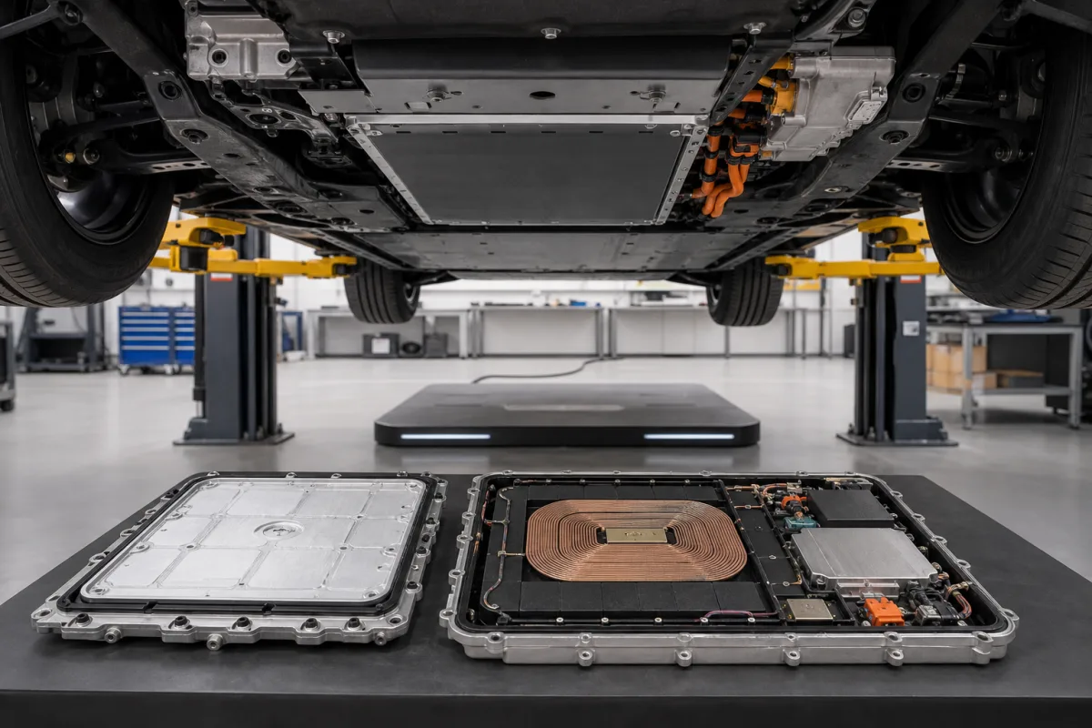
Vehicle assembly (VA) for wireless EV charging: the receiver pad and rectifier mounted under the car
The on-car half of wireless EV charging · SAE J2954 power class and 100–250 mm ground-clearance range, underbody space and weight, ferrite backing from −50 °C to 57 °C, and the 27 µT field limit at 0.8 m
A wireless-charging car carries one half of the charger on its own floor: a flat receiving pad that sits over the ground pad when the car is parked, and the power electronics that rectify what it picks up into battery current. SAE International calls this half the vehicle assembly (VA) and the parking-bay half the ground assembly (GA). For a vehicle engineer the VA is a packaging part as much as an electrical one — it has to match a power class and a ground-clearance range, fit the space and weight budget under the body, and keep its ferrite and field limits in an underbody environment.
The vehicle-side assembly of stationary inductive charging for passenger and light-duty electric vehicles: the underbody receiver coil and its ferrite and housing, the on-vehicle rectification to DC, the power class and ground-clearance range it is designed for, and its packaging under the car. Complete ground-plus-vehicle systems, EMF exposure rules and efficiency testing across gap and offset are covered on the Automotive wireless power transfer system page; foreign object detection over the ground pad is on the Foreign object detection for wireless EV charging page; AGV and mobile-robot charging pads on the Inductive charging module for AGVs and mobile robots page; Qi coils for phones on the Receiver coil assembly for Qi wireless charging page. Robots and lines that assemble vehicles are on the Assembly robot page.
CNFX editorial research · Sources checked October 12, 2026 · 3 sources
WPT1 to WPT3 and three ground-clearance ranges between 100 and 250 mm
SAE J2954, announced by SAE International in October 2020, specifies the vehicle and ground sides of wireless charging in one document. It sets three power levels — WPT1 at 3.7 kW, WPT2 at 7 kW and WPT3 at 11 kW — and three overlapping ranges of vehicle ground clearance spanning 100 to 250 mm (3.9 to 9.8 in). [1] A VA is therefore designed for a class and a clearance range taken from the vehicle's ride height.
SAE describes a universal ground assembly for WPT3 that is downward-compatible with WPT1 and WPT2 vehicles, so a VA built to any of the three classes can be charged at a public WPT3 bay; captive fleets may instead use a GA designed for a specific group of vehicles. [1]
Editorial calculation: the parking tolerance box is 150 mm long by 200 mm wide (±75 mm by ±100 mm), and WPT3 at 11 kW is about three times WPT1 at 3.7 kW (11 ÷ 3.7 ≈ 3.0).
Up to 94% grid-to-battery at a 250 mm (10 in) clearance [1]
A reference point for the highest clearance
Tell the VA supplier the J2954 power class, the vehicle's ground clearance at kerb weight and at full load, the parking tolerance the car's guidance can achieve, and whether the car must charge at public universal GAs or only at a captive-fleet GA.
02
Underbody space and weight: a 270 kW receiver in the bay sized for 11 kW
Oak Ridge National Laboratory explains why packaging governs the VA: a light-duty car such as the Porsche Taycan cannot carry conventional large, heavy wireless charging hardware because of space, weight and volume limits. ORNL reported in June 2024 that existing light-duty systems were being developed for up to 11 kW at up to 92% efficiency. [2]
ORNL's demonstration with Volkswagen Group of America transferred 270 kW to a Taycan through polyphase coupling coils with a diameter just over 19 inches, integrated into the vehicle's undercarriage, across a 4.75-inch gap between the ground and the vehicle-mounted coil. ORNL states the receiver coil reaches 8 to 10 times the power density of existing systems, can add 50% state of charge in 10 minutes at more than 95% efficiency, and that the on-board protection prevents exceeding voltage and current limits, overheating and short-circuiting. [2]
ORNL and Volkswagen named the next steps as a more cost-effective and manufacturable version and a lightweight enclosure improving mechanical, electrical, thermal and magnetic performance — the enclosure being the part a production VA must add around the coil. [2]
Editorial calculation: 19 inches is about 483 mm, and the 4.75-inch gap is about 121 mm, which lies inside the 100–250 mm clearance span SAE J2954 covers. [2][1] The 270 kW figure is a research demonstration, not a J2954 class.
Give the supplier the available underbody envelope (length, width, depth), the mass budget, the mounting points and crash or stone-strike zones, and ask for the VA mass, thickness and enclosure material.
03
Ferrite behind the receiver coil: permeability 2,550–3,727 from −50 °C to 57 °C, and a 27 µT limit at 0.8 m
Idaho National Laboratory, with ORNL and KEMET, measured the relative permeability of a KEMET BH1T ferrite sample (25 × 15 × 10 mm, tested at 100 kHz) from −50 °C to 240 °C, because charging pads and their ferrite shielding are exposed to outdoor cold and heat. [3]
From these data the INL simulations found no significant impact on electromagnetic shielding performance between −50 °C and 57 °C; the simulated case was in-motion road charging, which the authors say applies equally to stationary charging. [3] The same paper cites SAE J2954 as defining a maximum magnetic field of 27 µT at 0.8 m from the centre of the vehicle-side coil for light-duty stationary charging, derived from a 1.6 m vehicle width, and gives coupling coefficients between 0.1 and 0.5 for these loosely coupled coils. [3]
Editorial note: the 0.8 m boundary is measured from the VA coil centre, so where the pad sits across the car's width matters; a pad moved off the centreline brings one side of the car closer to the field. Ask for the field map with the pad in its actual position under the body.
After the coil: AC-to-DC conversion on the car and the handshake that starts charging
SAE describes the power path: after a communications handshake, the field between the ground pad and the receiving pad on the vehicle's underside carries energy across the air gap, and it is converted from AC into DC on the vehicle to charge the battery. [1]
To prove interoperability, SAE standardised a GA/VA test station and coil specifications; bench tests at DOE's Idaho National Laboratory and at TDK RF Solutions first measured matched subsystems from one maker, then GAs and VAs from different makers, reporting input and output power, power factor, efficiency and maximum power to the load across output voltages, misalignments and clearances. SAE reports the non-matched pairs performed similarly to matched ones. [1] FDA testing with running pacemakers led to the public-infrastructure GA being a circular coil topology. [1]
Editorial note: a VA built for interoperability should come with test data against the J2954 reference GA, not only against the maker's own ground pad; ask for both.
Ask for the VA's output voltage range against your battery voltage window, the rectifier's cooling path, the communication protocol used for the handshake, and interoperability results against a non-matched GA.
05
What to give a supplier for a wireless-charging vehicle assembly
Paste it into your enquiry below or into an email to a maker, then replace every bracket.
Vehicle: [model; battery voltage window; ground clearance unladen and laden]
Class: [WPT1 / WPT2 / WPT3; public universal GA or captive-fleet GA]
Package: [underbody envelope L × W × D; mass budget; mounting points; position across the width]
Environment: [temperature range; water, salt and stone exposure]
Electrical: [output voltage and current; rectifier cooling; communication protocol]
Evidence: [interoperability test against a reference GA; field map at 0.8 m; ferrite and enclosure data]
Explore company information and manufacturing capabilities, then discuss the scope of your project with a relevant supplier.
Share this page
Compiled and source-reviewed by the CNFX editorial team.
Each manufacturer above links to the page on that company's own website where the product is listed, with the date we checked it. How we source and review
· Page last updated 13 October 2026
Buyer questions
What is a vehicle assembly in wireless EV charging?
In SAE J2954 it is the on-vehicle side: a receiving pad under the car and the equipment that converts the captured AC into DC for the battery; the ground side is the ground assembly. [1]
What ground clearance does SAE J2954 cover?
Three overlapping ranges spanning 100 to 250 mm, with parking tolerances of ±75 mm along and ±100 mm across the direction of travel. [1]
How big can a high-power receiver be?
ORNL's 270 kW receiver for a Porsche Taycan used polyphase coils just over 19 inches in diameter, mounted under the car across a 4.75-inch gap. [2]
Does cold weather affect the ferrite shielding?
INL measured permeability falling from 3,074 at 0 °C to 2,550 at −50 °C and simulated no significant change in shielding between −50 °C and 57 °C. [3]
Sources and what still needs a direct check
Sources checked 2026-10-12. Power classes, clearance ranges, tolerances and the interoperability test programme come from SAE International's announcement of SAE J2954; underbody packaging and the 270 kW receiver from Oak Ridge National Laboratory's report of its Porsche Taycan demonstration; ferrite permeability against temperature and the 27 µT boundary from an Idaho National Laboratory conference paper written with ORNL and KEMET.