Editorial Technical Reference

Load Cell & Verification System

This page explains how Load Cell & Verification System is classified within Other Transport Equipment Manufacturing. Technical values and manufacturer relationships are research references; confirm the current specification and supplier evidence for each order.

Technical Definition & Core Assembly

A precision measurement and validation subsystem for propellant mass in metering and charging operations
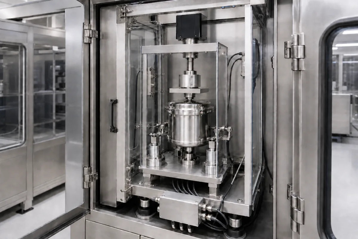
Representative product image. Confirm appearance and specifications with the manufacturer.

Product Specifications

Technical details and manufacturing context for Load Cell & Verification System

Definition
The Load Cell & Verification System is a critical subsystem within the Precision Propellant Metering and Charging Station. It combines high-accuracy load cells with integrated verification mechanisms to ensure precise measurement, monitoring, and validation of propellant mass during transfer and charging processes. This subsystem maintains strict quality control and safety standards by providing real-time weight data and performing automated checks to confirm measurement integrity. The system is designed for use in other transport equipment manufacturing, where precise propellant dosing is essential. It features a rated capacity range of 50–500 kg, selectable based on the maximum propellant mass per charge. Accuracy classes C3 to C6 per OIML R60 are available, with C6 recommended for high-precision dosing. Nonlinearity is ±0.02–±0.05%FS, repeatability ±0.01–±0.03%FS, and creep (30 min) ±0.02–±0.05%FS. Temperature effects on zero and span are ±0.01–±0.03%FS/10K, and the operating temperature range is -40 to 85°C. Excitation voltage is 5–12 V DC, insulation resistance is ≥5000 MΩ at 50 V DC per IEC 60255-5, and ingress protection is IP65–IP68 per IEC 60529. The material is 17-4PH stainless steel per ASTM A564, with safe overload of 150%FS and ultimate overload of 300%FS. The system includes verification features such as calibration checks, zero-point validation, and measurement accuracy confirmation through reference standards or redundant measurement techniques. It is essential to verify model-specific values and standards with the legal manufacturer or supplier before procurement.
Working Principle
The system uses strain gauge-based load cells to convert the applied force from propellant weight into electrical signals. These signals are processed to determine mass. The verification subsystem performs calibration checks, zero-point validation, and accuracy confirmation using reference standards or redundant measurement techniques. This ensures that the load cells maintain accuracy over time and under varying conditions. The system is designed to operate within specified temperature ranges and environmental conditions, with ingress protection up to IP68 for harsh environments. Regular verification is critical to maintain measurement integrity and safety.
Common Materials
Stainless steel, Aluminum alloy, Strain gauge elements, Electronic components
Technical Parameters
ParameterTypical rangeNotes & selection driver
Rated Capacity50–500 kgSelect based on max propellant mass per charge
Accuracy ClassC3–C6C3 for standard, C6 for high-precision dosingOIML R60
Nonlinearity±0.02–±0.05 %FSLower is better for linearity
Repeatability±0.01–±0.03 %FSCritical for consistent charging
Creep (30 min)±0.02–±0.05 %FSAffects long-term stability during hold
Temperature Effect on Zero±0.01–±0.03 %FS/10KMinimize for outdoor or variable temp
Temperature Effect on Span±0.01–±0.03 %FS/10KAffects accuracy over temperature range
Operating Temperature Range-40–85 °CWider range for harsh environments
Excitation Voltage5–12 V DCTypical 10 V DC; check compatibility
Insulation Resistance≥5000 At 50 V DC; ensures safetyIEC 60255-5
Ingress ProtectionIP65–IP68IP68 for washdown or submersionIEC 60529
Material17-4PHStainless steel for corrosion resistanceASTM A564
Safe Overload150 %FSWithout permanent damage
Ultimate Overload300 %FSMechanical failure limit

Ranges are indicative industry figures for RFQ preparation, not a supplier commitment. Confirm every value and standard with the legal manufacturer before ordering.

Components / BOM
  • Load Cell Assembly
    Converts propellant weight into electrical signals for measurement
    Material: Stainless steel
  • Signal Conditioner
    Amplifies and processes load cell output signals
    Material: Electronic components
  • Verification Mechanism
    Performs calibration checks and accuracy validation
    Material: Aluminum alloy
  • Mounting Frame Part
    Provides structural support and alignment for load cells
    Material: Steel

Applied To / Applications

This component is essential for the following industrial systems and equipment:

Industrial Ecosystem & Supply Chain Structure

Complementary Systems
Downstream Applications
Specialized Tooling

Application Fit & Sizing Matrix

Operational Limits
pressure: 0 to 100 bar
flow rate: 0.1 to 100 L/min
temperature: -40°C to +85°C
slurry concentration: 0-60% solids by weight
Media Compatibility
✓ Hydrazine-based propellants ✓ Liquid oxygen (LOX) ✓ Hydrogen peroxide (H2O2)
Unsuitable: Hydrofluoric acid environments
Sizing Data Required
  • Maximum propellant mass per batch (kg)
  • Required measurement accuracy (% of full scale)
  • Process cycle time (seconds)

Reliability & Engineering Risk Analysis

Failure Mode & Root Cause
Zero drift or calibration shift
Cause: Temperature fluctuations, mechanical stress from overloading, or moisture ingress affecting strain gauge circuitry
Signal noise or intermittent readings
Cause: Loose electrical connections, electromagnetic interference (EMI) from nearby equipment, or damaged cable shielding
Maintenance Indicators
  • Erratic or fluctuating readings during verification cycles
  • Audible buzzing or crackling from the load cell or junction box
Engineering Tips
  • Implement regular calibration schedules using traceable standards and document environmental conditions (temperature, humidity) during verification
  • Ensure proper cable management with shielded cables, secure connections, and protection from physical damage or exposure to contaminants

Indicative industry ranges for design and RFQ preparation. Confirm the exact figures and applicable standard with the manufacturer before specifying.

Compliance & Manufacturing Standards

Applicable Standards
ISO 376:2011 - Calibration of force-proving instruments used for the verification of uniaxial testing machines ASTM E74-18 - Standard Practice of Calibration of Force-Measuring Instruments for Verifying the Force Indication of Testing Machines EN 10002-3:1995 - Metallic materials - Tensile testing - Part 3: Calibration of force proving instruments used for the verification of uniaxial testing machines

Quoted from the published standard.

Manufacturing Precision
  • Linearity: +/-0.03% of full scale output
  • Hysteresis: +/-0.02% of full scale output
Quality Inspection
  • Shunt Calibration Test
  • Creep Test

Manufacturers of Load Cell & Verification System

Manufacturer profiles associated with Load Cell & Verification System.

Sourcing Load Cell & Verification System from China?
Tell us your specification and target quantity — we will match it against manufacturer records and come back with the factories that fit.
Request manufacturers We manufacture this

Manufacturer listings support early research and capability understanding. They are not certification, ranking, or transaction guarantees.

Technical documentation
Request current drawings, revision history, and a signed specification sheet.
Manufacturing capability
Verify equipment lists, process limits, capacity, and representative production evidence.
Inspection readiness
Confirm test methods, calibrated equipment, sampling plans, and traceable reports.
Supplier transparency
Check the legal entity, factory address, ownership, certifications, and direct contacts.

CNFX does not score or rank suppliers. Buyers must verify all claims and documents with the legal manufacturer before ordering.

Supply Chain Compatible Machinery & Devices

Aerospace Turbine Blades

High-precision airfoil components that extract energy from high-temperature, high-pressure gas streams to drive aerospace turbine engines.

Explore Specs →
Marine Propeller Shaft Seal

A marine propeller shaft seal is a critical component installed at the point where the propeller shaft penetrates the ship's hull.

Explore Specs →
Marine Hull Plate Bending Roller

The Marine Hull Plate Bending Roller is a heavy-duty industrial machine used in shipbuilding to precisely bend and form thick steel plates into curved hull sections through controlled rolling pressure.

Explore Specs →
Marine Hull Plate Shot Blasting Machine

Industrial machine for surface preparation of ship hull plates via abrasive blasting

Explore Specs →

Frequently Asked Questions

What is the rated capacity range of the Load Cell & Verification System?

The rated capacity is 50–500 kg, selected based on the maximum propellant mass per charge. Confirm the exact capacity with the manufacturer for your application.

What accuracy classes are available?

Accuracy classes C3 to C6 per OIML R60 are available. C6 is recommended for high-precision dosing. Verify the class required for your process.

What is the operating temperature range?

The operating temperature range is -40 to 85°C. For outdoor or variable temperature environments, consider the temperature effects on zero and span, which are ±0.01–±0.03%FS/10K.

What ingress protection ratings are offered?

Ingress protection is IP65–IP68 per IEC 60529. IP68 is suitable for washdown or submersion. Confirm the required rating for your installation environment.

Data Basis

Editorial classification, named public sources where available, and source-reviewed manufacturer records.

Preliminary Technical Classification
This page supports structured research, RFQ preparation, and supplier evaluation. It does not replace buyer-led supplier qualification, standards review, or technical approval.
Buyer enquiry

Request manufacturing insight for Load Cell & Verification System

Ask for use case, specification boundaries, supplier type, and RFQ preparation information for this product.

Where it goes
Straight to the CNFX editorial desk, and to the manufacturer if this product is linked to a claimed profile. Nothing is broadcast to a supplier list.
Your details stay here
We do not sell or rent enquiry data, and we do not add you to a mailing list. Used only to answer this request.
No commission, no middleman
CNFX is a directory. We take no cut of any order and never negotiate on a supplier's behalf.
What we don't claim
A listing is not an endorsement. Qualify every supplier and verify every figure yourself before ordering.

Your business information is used only to process this request.

Thank you! Your message has been sent. We'll respond within 1–3 business days.
Sorry, we couldn't send your message. Please try again, or email us at contact@cnfx.com.

Need to Manufacture Load Cell & Verification System?

Compare manufacturer profiles with relevant product and process capability.

Previous Product
Winch Control Module
Last Product
Get QuotesChat