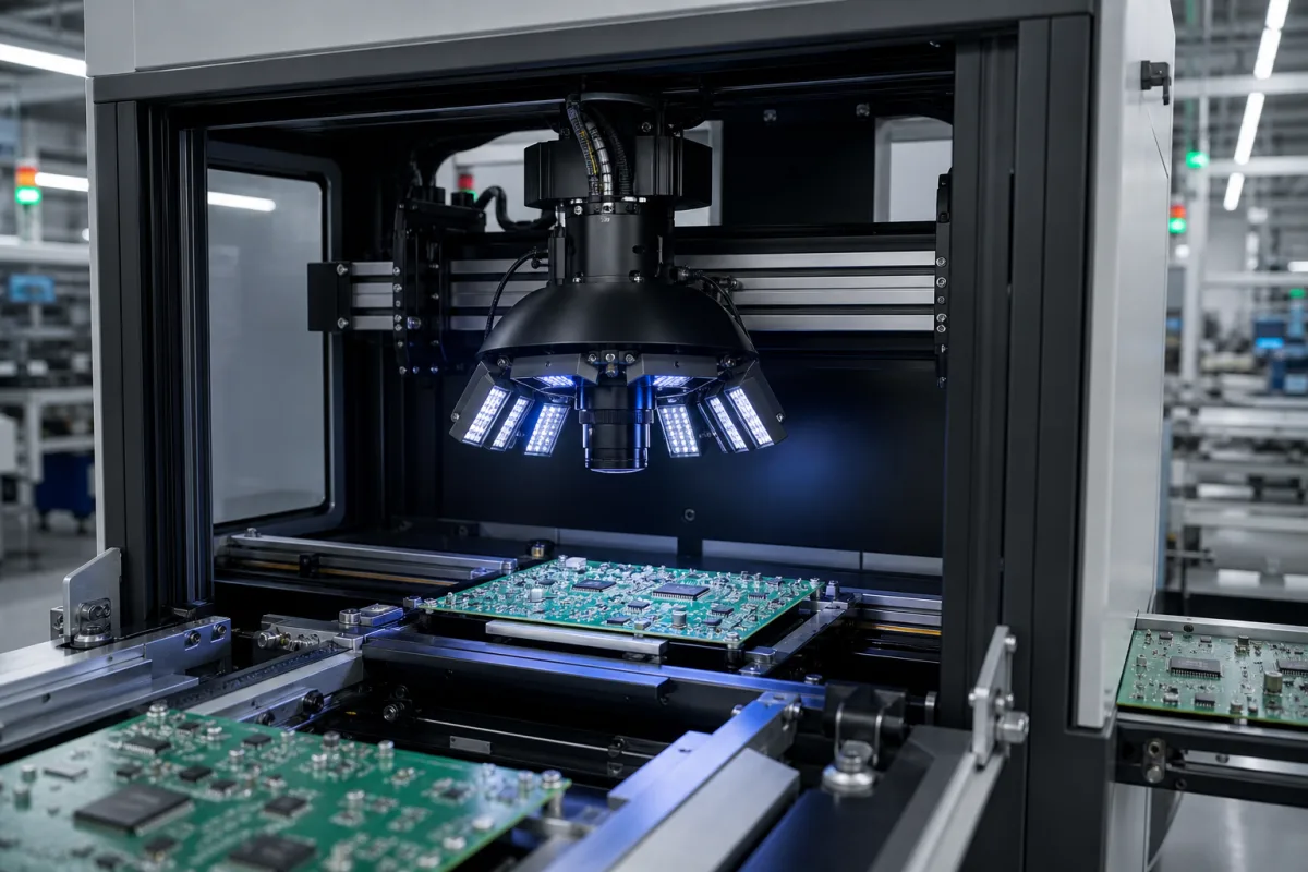
Bottom-side and double-sided AOI system for through-hole solder joints
Through-hole solder inspection · bottom-side and double-sided AOI after wave and selective soldering, solder-side clearance, hot and heavy boards
A bottom-side or double-sided AOI system is an in-line optical inspection machine with a camera head under the conveyor, alone or paired with a top head, that checks through-hole (THT) solder joints and pins on the solder side of a board after wave or selective soldering without turning the board over. Ask three things first: how much clearance the bottom head leaves for pins and pallets, whether the transport accepts boards still warm and heavy from the solder machine, and how long the machine needs per field of view on your board.
In-line AOI machines that inspect the solder side of through-hole and mixed-technology assemblies after wave or selective soldering, with an inverted (bottom) camera head or simultaneous top-and-bottom heads. Top-side AOI for SMT assemblies before or after reflow is covered on the Automated optical inspection (AOI) system for PCB assembly page. Solder paste inspection, X-ray inspection, bare-board AOI and the soldering machines themselves are outside this page.
CNFX editorial research · Sources checked October 12, 2026 · 3 sources
Check solder-side clearance and what the bottom head looks for
Reaching describes its inverted-camera AOI-V5200 series as installed at the bottom side of the line to inspect post-reflow and wave-soldered joints, THT components and odd-form parts without flipping the PCB; it lists top clearance of 120 mm and bottom clearance adjustable from 25 to 50 mm. [1]
Its double-sided VS5300 series inspects top and bottom surfaces in one pass; the data table for its VS300 and VS300XL models gives component clearance of 25–85 mm on top and 25–80 mm underneath. [2] Mek's ISO-Spector X1, a bottom-up 3D AOI designed for post-wave and selective soldering, offers 100 mm (3.9 in) of THT solder-side clearance and a 60 × 60 mm field of view, according to the launch report in Electronics For You. [3]
The defect lists show what the solder-side view adds. Reaching's wave-solder algorithm checks for insufficient solder, missing pins and blowholes on manually or machine-inserted through-hole parts. [1] Mek states that the X1 captures volumetric data for each solder joint and pin to detect pin height variations, annular ring coverage and blow holes. [3]
Editorial note: measure the longest pin protrusion, any selective-solder pallet or carrier, and the tallest bottom-side part, and compare them with the bottom clearance of the machine before asking for a demonstration.
Give the supplier board size and thickness, longest pin protrusion below the board, pallet or carrier height, top and bottom component heights, board temperature and weight at the AOI, soldering process (wave or selective), defects to detect, cycle time, and line interface (SMEMA, MES).
02
Match the transport to hot and heavy boards, then estimate board time
Boards leaving a wave or selective solder machine may still be warm and may ride on heavy carriers, so the conveyor limits matter. Reaching's VS300 data table allows boards up to 10 kg at up to 60 °C on the standard belt, rising to 30 kg and 150 °C with the optional roller pulley; its inverted V5200 uses roller-pulley transport with a 3.0 kg board weight limit. [2][1]
Both Reaching series use 5 MP or 12 MP cameras with telecentric lenses and four-colour (RGBW) ring LEDs, with a field of view of 60 × 49 mm at 24 µm (5 MP) or 60 × 45 mm at 15 µm (12 MP). Inspection takes 200–250 ms per field of view on the double-sided VS300 and 180–200 ms on the V5200. [2][1] Mek's X1 accepts boards up to 550 × 550 mm, including pallets. [3]
Editorial calculation (assumptions: a full 510 × 510 mm board, 60 × 49 mm fields tiled without overlap, motion and board transfer time ignored): 510 ÷ 60 = 8.5, so 9 columns; 510 ÷ 49 = 10.4, so 11 rows; 9 × 11 = 99 fields × 0.20–0.25 s = about 20–25 s of imaging per side on the VS300. Ask the supplier to time your own board, since through-hole boards may only need the solder-joint areas imaged.
03
Compare inverted, double-sided and 3D bottom-up designs
Field of view, pixel resolution, board temperature and weight for a solder-side AOI
Throughput is not published as boards per hour: the Reaching tables give 180–250 ms per field, so the rate depends on how many fields your board needs. Humidity range and IP rating are not stated in the reviewed sources.
Field
What it means and published values
Ask the supplier for
Field of View (mm)
60 × 49 or 60 × 45 mm (Reaching); 60 × 60 mm (Mek). [2][3]
Compare bottom-side and double-sided AOI suppliers
1 company lists this product among what they make. Company figures are quoted from each
company's own website; every card states where the relationship came from.
Shenzhen Reaching Electronic Assembly Co., Ltd.
Manufacturing site to be confirmed for the order
Lists inverted-camera (bottom-side) and double-sided AOI systems for wave-soldered and through-hole boards, alongside top-side SMT AOI.
Explore company information and manufacturing capabilities, then discuss the scope of your project with a relevant supplier.
Share this page
Compiled and source-reviewed by the CNFX editorial team.
Each manufacturer above links to the page on that company's own website where the product is listed, with the date we checked it. How we source and review
· Page last updated 13 October 2026
Buyer questions
Why inspect through-hole joints from below?
The solder joints of wave- or selective-soldered parts are on the bottom; Reaching's inverted AOI inspects them at the bottom side of the line without flipping the board. [1]
How much clearance does the bottom head need?
Published values range from 25–50 mm adjustable (Reaching V5200) and 25–80 mm (Reaching VS300) to 100 mm (Mek ISO-Spector X1). [1][2][3]
What defects does a THT AOI look for?
Reaching lists insufficient solder, missing pins and blowholes; Mek adds pin height variations and annular ring coverage from 3D data. [1][3]
Sources and what still needs a direct check
Sources checked 2026-10-12. Reaching (a listed supplier) publishes its own machine tables; the Mek details come from a trade-press launch report. Values are maker statements, not independent tests.