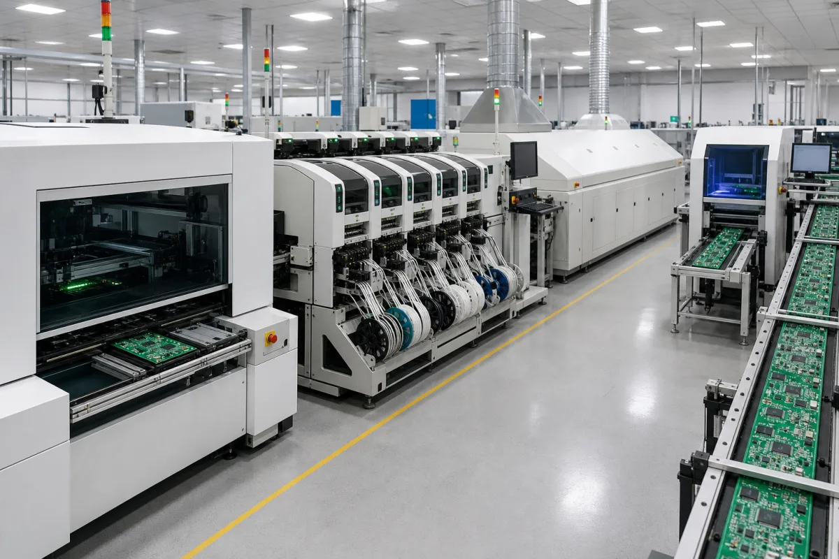
Automated printed circuit board assembly line for mixed SMT and through-hole boards
Mixed-technology PCB assembly · automatic through-hole insertion and selective soldering after the SMT section
An automated printed circuit board assembly line, in the sense used on this page, assembles boards that carry both surface-mount and through-hole parts: after paste printing, placement and reflow, the boards move on to machines that insert leaded components and solder them from below, then to inspection and test. Ask three things first: which through-hole parts can be inserted automatically and which stay manual, how the leaded joints are soldered without damaging the surface-mount parts already on the board, and how much solder contact time the board's copper can take.
Automated lines for mixed-technology boards that add through-hole stages (radial or axial insertion, selective or wave soldering) and test after the surface-mount section. Lines made only of surface-mount machines (loader, paste printer, placement, reflow, inspection) are covered on the Automated SMT assembly line page. PCB assembly services, bare-board fabrication and battery or LED lighting lines are outside this page.
CNFX editorial research · Sources checked October 12, 2026 · 3 sources
Decide which through-hole parts are inserted automatically
Universal Instruments' Radial 88HTi datasheet lists a throughput of 20,000 cph for radial-lead parts (capacitors, LEDs, transistors, resistors, connectors), with single, dual, triple and quad-span tooling covering lead spans of 2.5 to 10.0 mm, 20 to 100 component inputs in steps of 20, and servo heads that insert at any angle in 1° steps. [1]
The same datasheet gives board sizes of 102 × 80 mm to 483 × 406 mm with automatic loading (51 × 51 mm to 600 × 600 mm manual), a 2-second board exchange in pass-through, reliability of 300 ppm or better for single and dual span and 400 ppm for triple and quad span, a single-phase 180–246 V, 1,150 VA supply, and a programmable insertion height to avoid damaging surface-mount components already on the board. [1]
Editorial calculation: at 20,000 cph, one insertion takes 0.18 s; a board with 60 radial parts would take about 11 s of insertion before board exchange. Compare that with the SMT section's cycle time for the same board to see whether the insertion stage paces the line.
Give the supplier the board size and thickness, the list of through-hole parts with lead spans and package type (radial, axial, connectors, odd-form), parts per board, boards per hour, which parts may stay manual, the solder alloy, and the test steps required at the end of the line.
02
Solder the leaded parts after reflow without eroding the copper
In a paper on lead-free selective soldering, ACE Production Technologies reports that Sn-Ag-Cu dissolves copper at an average 0.020 mils per second of contact time, double the 0.010 mils/s of Sn-Cu-Ni, against 0.005 mils/s for tin-lead, and that the recommended maximum cumulative through-hole contact time, including wave soldering and rework, is 45 seconds. [3]
ACE writes that with sustained topside preheat the solder pot temperature can be lowered from 300–320 °C to 260–280 °C, that the best results come with topside board temperature of 110–120 °C, and that fluxes must withstand topside temperatures of 130 °C or higher and solder at 280 °C or higher for at least 3–4 seconds of contact. It recommends that pot analysis keep copper below 1.0%, iron below 0.02% and lead below 0.1% by weight. [3]
Kurtz Ersa's VERSAFLOW 3/66 inline selective soldering platform takes boards of 63.5 to 610 mm width and 127 to 610 mm length, up to 5 kg (15 kg optional), with 120 mm top and 60 mm bottom clearance, up to three soldering modules with one or two single-wave pots holding 13 kg of solder each, up to five bottom preheat modules, and drop-jet fluxing with up to four heads; the machine is 2,950 × 1,900 × 1,650 mm. [2]
Editorial calculation: at ACE's 0.020 mils/s for Sn-Ag-Cu, 45 s of cumulative contact would remove about 0.9 mil (about 23 µm) of copper, in line with ACE's report that rework can consume as much as 0.8 mils, about half the average copper thickness. [3]
03
In-house or integrated through-hole stages after SMT
Ask each supplier which through-hole stages (insertion, selective or wave soldering, test) they supply themselves and which they integrate from other makers, and how boards and data pass between the SMT and through-hole sections.
04
From the SMT section through fluxer, preheat and solder pot to final test
Stage
Role
Fix in the order
SMT section
Paste printing, placement, reflow; see the SMT line page.
Machines and cycle time.
Radial or axial insertion
Inserts and clinches leaded parts; 2.5–10.0 mm spans listed. [1]
Lines on offer pair SMT pick-and-place, stencil printing and reflow with through-hole stations (DIP machines, wave and selective wave soldering), with AOI or ICT/FCT testing at the end.
CHARMHIGH TECHNOLOGY LIMITED
Manufacturing site to be confirmed for the order
Lists PCB assembly lines built from its pick-and-place machines, stencil printers and reflow ovens, and lists wave soldering machines, loaders, conveyors and AOI.
Explore company information and manufacturing capabilities, then discuss the scope of your project with a relevant supplier.
Share this page
Compiled and source-reviewed by the CNFX editorial team.
Each manufacturer above links to the page on that company's own website where the product is listed, with the date we checked it. How we source and review
· Page last updated 13 October 2026
Buyer questions
How fast can radial through-hole parts be inserted automatically?
Universal Instruments lists 20,000 cph for its Radial 88HTi over 2.5–10.0 mm lead spans. [1]
Why limit solder contact time on through-hole joints?
ACE reports Sn-Ag-Cu dissolves copper at 0.020 mils/s and cites a 45 s cumulative contact-time limit. [3]
How large a board can a selective soldering machine take?
Ersa's VERSAFLOW 3/66 takes boards up to 610 × 610 mm and 5 kg (15 kg optional). [2]
Sources and what still needs a direct check
Sources checked 2026-10-12. Universal Instruments and Kurtz Ersa are equipment makers publishing their own machine data; the ACE Production Technologies paper is a maker's technical paper on lead-free selective soldering.