RF and microwave · Passband and rejection, insertion loss and resonator Q, VSWR, power and filter technology
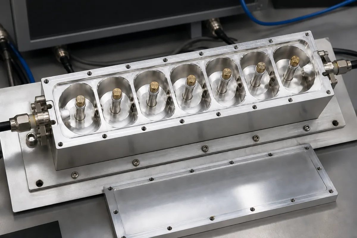
An RF band-pass filter passes a band of frequencies and attenuates those outside it, using resonators such as metal cavities, ceramic or LC circuits, or acoustic-wave devices. Ask three things first: the passband and the rejection needed at specific frequencies, the insertion loss and VSWR allowed in the passband, and the power, connectors and environment it must handle.
RF and microwave band-pass filters: cavity, combline, waveguide, ceramic, LC, SAW and thin-film types, connectorised or surface-mount. Optical band-pass filters, low-pass, high-pass and band-stop filters, and power-line EMI filters are outside this page.
CNFX editorial research · Sources checked October 11, 2026 · 5 sources
Read a band-pass filter specification: a worked example
Chengdu Leader Microwave lists a cavity band-pass filter, type LBF-995/10-2S, with a 990–1,000 MHz passband, VSWR ≤ 1.3:1, insertion loss ≤ 0.6 dB, rejection ≥ 60 dB from DC to 920 MHz and from 1,070 to 2,000 MHz, 40 W power handling and SMA-female connectors. The same page lists other filters, for example 1,450–1,478 MHz with ≤ 2.0 dB loss and a 26.5–40 GHz cavity filter with ≤ 1.0 dB loss. [1]
Editorial calculation: a 10 MHz passband at 995 MHz is about 1.0% fractional bandwidth, and the 60 dB rejection limits start 70 MHz from each band edge. Insertion loss of 0.6 dB passes 10^(−0.06) ≈ 87% of the power, so at 40 W input about 5 W is dissipated in the filter as heat. [1] Specify rejection at the frequencies that matter to your system and ask for loss and rejection over temperature.
Give the supplier the passband edges, maximum insertion loss and ripple, minimum rejection at listed frequencies, VSWR or return loss, input power (average and peak), impedance, connectors or mounting, size limits, and operating temperature and environment.
02
Understand why narrow filters need high-Q resonators
Lecture notes on resonators from the University of California, Santa Barbara define unloaded Q (QU) as the resonator's own losses and loaded Q (QL) as set by the external circuit, with bandwidth = ω₀ ÷ QL. For a single resonator used as a band-pass filter, insertion loss = −20 log(1 − QL ÷ QU) dB, so narrow bandwidth, where QL approaches QU, can be very lossy. [2]
Editorial calculation: a single resonator at 900 MHz with 9 MHz bandwidth has QL = 100; with QU = 5,000 the loss is −20 log(1 − 0.02) ≈ 0.18 dB, but with QU = 500 it is about 1.9 dB. [2] Ask the supplier for the resonator type and its unloaded Q.
Suppliers on this page offer cavity, LC, SAW and thin-film technologies. [1][3]
03
Read rejection against distance from the band edge
Anatech Electronics publishes its cavity band-pass filters as a catalogue table with centre frequency, bandwidth, maximum insertion loss, passband, high-side and low-side rejection and return loss, which shows how far from the passband each rejection figure applies. In the 1,001–2,000 MHz range, model AE1227B12117 passes 1,215.6–1,239.6 MHz with 1.0 dB maximum loss and gives 50 dB minimum rejection at 1,268.52 and 1,186.68 MHz; AE1575B12118 passes 1,555.42–1,595.42 MHz with 1.0 dB maximum loss and 50 dB minimum at 1,616.34 and 1,534.50 MHz; and AE1650B11999 passes 1,625–1,675 MHz with 2.5 dB maximum loss and 70 dBc minimum from 1,700 to 2,150 MHz. [4] A separate product page lists a 1,870–1,980 MHz filter with 110 MHz bandwidth, more than 40 dB rejection at 1,990 and 1,860 MHz, return loss over 15 dB, N-type (F) connectors and 6.3 × 2.64 × 1.3 in dimensions. [5]
Editorial calculation: the rejection points sit 28.92 MHz outside each band edge for AE1227B12117, 20.92 MHz for AE1575B12118, 25 MHz above the band for AE1650B11999 and 10 MHz for the 1,870–1,980 MHz filter. The AE1650B11999, with the highest rejection close to its band, also carries the highest listed loss (2.5 dB against 1.0 dB), which matches the resonator Q trade-off described in the UCSB notes. [4][2]
When you compare quotations, ask for rejection at named frequencies, not a single dB figure, and check whether the loss figure is a maximum across the passband or a value at centre frequency. [4]
Anatech model
Passband and max loss
Rejection point
Editorial calculation: offset from band edge; fractional bandwidth
Fill the specification fields with values for your system
A band-pass filter quotation needs values for your signal chain. The table explains each field, gives published values where a reviewed source states them, and says what to obtain from the supplier.
Explore company information and manufacturing capabilities, then discuss the scope of your project with a relevant supplier.
Share this page
Compiled and source-reviewed by the CNFX editorial team.
Published product pages show what a company offers, not tested performance. Confirm the legal seller, factory and scope for your order. How we source and review
· Page last updated 13 October 2026
Buyer questions
Why do narrow band-pass filters have more loss?
For a resonator, insertion loss is −20 log(1 − QL/QU); narrow bandwidth raises QL towards QU and loss rises. [2]
How much power does a 0.6 dB filter dissipate?
About 13% of the input; at 40 W, about 5 W (editorial calculation). [1]
Which technologies are used for RF band-pass filters?
Suppliers here list cavity, LC, SAW and thin-film filters. [1][3]
How close to the passband can a cavity band-pass filter reject?
Anatech's catalogue lists 50 dB minimum rejection 20.92 MHz outside a 1,555.42–1,595.42 MHz passband with 1.0 dB maximum loss, and over 40 dB just 10 MHz outside a 1,870–1,980 MHz passband (editorial calculation of the offsets). [4][5]
Sources and what still needs a direct check
Sources checked 2026-10-11. The UCSB notes are university teaching material on resonator theory. Chengdu Leader Microwave is a supplier listed on this page; its specification is used as a worked example. Anatech Electronics' cavity filter catalogue gives further rejection and loss figures by model.