Handset receiver transducer: the dynamic earpiece capsule of a desk phone handset, its telecoil field and receive level
The receiver (earpiece) capsule inside a desk phone handset · 150 Ω dynamic units of 38 mm, the magnetic field a hearing-aid telecoil picks up, the 18–24 dB receive volume range, and the ear simulators it is measured on
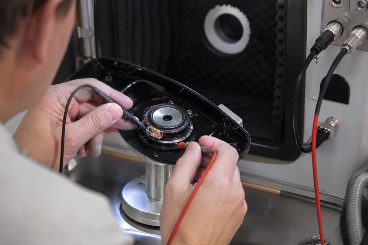
The handset of a desk phone carries two transducers, and this page is about the one at the ear: the receiver, a small dynamic loudspeaker capsule in the earcap. It has to be loud enough on an ear-sized coupler, leak a usable magnetic field for hearing aids with telecoils, survive drops and heat, and be measured the same way at the capsule maker, the phone maker and the test lab.
Receiver (earpiece) transducers for telephone handsets: dynamic receiver capsules, their impedance, sensitivity and environmental tests, the magnetic field they must provide for hearing-aid telecoils, the receive volume range of the handset, and the ear simulators used to measure them. Complete SIP desk phones, with PoE power, codecs and network interfaces, are covered on the Enterprise VoIP desk phone page; loudspeaker drivers for sound reinforcement on the Speaker driver (loudspeaker transducer) for professional and commercial sound page. Handset microphones, headsets and mobile phone receivers are outside this page except where a mobile receiver is used for comparison.
CNFX editorial research · Sources checked October 12, 2026 · 5 sources
A 38 mm, 150 Ω handset receiver beside a 12 × 6 mm, 32 Ω mobile receiver
Two capsule specifications show how differently a desk handset receiver and a mobile phone receiver are rated, even when both are measured on the same IEC 318 coupler. [1][2]
Editorial calculation: 60 mV across 150 Ω is (0.06)² ÷ 150 = 24 µW; 179 mV across 32 Ω is (0.179)² ÷ 32 = 1.0 mW, which is why Soberton describes its measuring condition as 1 mW. The two sensitivity figures are therefore taken at drive powers about 42 times apart and cannot be compared directly.
The SD-150 sheet also has a line for magnet field intensity, axial and radial at 1 kHz, but the values on this approval sheet are left blank. [1] Ask for measured field values on any capsule intended for a hearing-aid compatible handset (next section).
No buzz or rattle at 1 V sine, 300 Hz to 3.4 kHz [1]
No buzz or rattle 200 Hz to 3.4 kHz, up to 0.56 Vrms [2]
Temperature tests
96 h at +70 °C and at −40 °C; cycles −40/+70 °C [1]
96 h at +60 °C and at −20 °C; operating −20 to +60 °C [2]
Drop test
In a handset, 18 drops from 1 m onto a 5 mm board [1]
In a 100 g dummy set, 6 drops from 1.5 m onto concrete [2]
Give the capsule supplier the handset earcap dimensions, the drive circuit's output voltage and impedance, the required level on the coupler, whether a telecoil field is required, and the environmental and drop tests the phone must pass.
02
Field for hearing-aid telecoils: axial above −22 dB re 1 A/m and radial above −27 dB, 10 mm in front of the earcap
In the United States a handset is hearing aid compatible if it meets the EIA RS-504 criteria reproduced in 47 CFR 68.316. They define a reference plane where the handset rests against the ear and a measurement plane 10 mm in front of it, on an axis through the centre of the receiver cap that may be moved by up to 10 mm. [3]
The standard notes that the measured field will be about 15 dB above the average level met in the field, and that hearing aids pick it up with an optional inductive pick-up coil, the telecoil. [3] Editorial calculation: −22 dB re 1 A/m is 10^(−22/20) ≈ 0.079 A/m, −19 dB ≈ 0.112 A/m and −27 dB ≈ 0.045 A/m.
Editorial note: the field comes from the receiver's magnet and voice coil, so it depends on the capsule chosen, its position behind the earcap and nearby steel parts; a capsule specification that leaves the axial and radial field blank, as the SD-150 sheet does, gives the phone designer nothing to check against these limits. [1]
Requirement in 47 CFR 68.316
Limit
Axial field at the measurement plane, −10 dBV input at 1,000 Hz
Induced voltage frequency response, 300 to 3,300 Hz
Within the Fig. 4A mask if axial exceeds −19 dB; Fig. 4B mask if between −22 and −19 dB [3]
Feed circuit for the measurement
1,250 Ω resistor in series with the battery feed instead of 2.75 km of 26 AWG cable; equivalent feed for digital telephones [3]
03
Receive volume through the handset receiver: 18 to 24 dB conversational gain at the loudest setting
47 CFR 68.317 sets how much louder the receiver must be able to play than its normal level. For telephones made or imported for use in the United States on or after 28 February 2020, the loudest volume setting must give a conversational gain of at least 18 dB and at most 24 dB, measured by ANSI/TIA-4965-2012, with the 18 dB reached without significant clipping. [4]
The 24 dB maximum may be exceeded only if the amplified level resets automatically to not more than 24 dB when the phone goes on-hook, to protect people with normal hearing. [4] Under the earlier rules for telephones before that date, the requirement was 12 dB minimum and 18 dB maximum of gain in Receive Objective Loudness Rating, measured from 300 to 3,300 Hz; for analogue phones over 0, 2.7 and 4.6 km of 26 AWG cable. [4]
Editorial note: 18 dB of extra gain without clipping is a requirement on the receive amplifier and the receiver together; a capsule with too little sensitivity forces the amplifier toward clipping before the gain is reached, so check the capsule's level and power rating against the amplifier's maximum output.
04
Measuring the receiver: IEC 60318-4 coupler, low-leak and high-leak pinna simulators
Brüel & Kjær's Wideband Ear Simulator Type 4195 shows what a receiver is measured against in telephonometry: an IEC 60318-4 coupler with a ½-inch microphone, plus a simplified pinna with an ear-canal extension and a cavity whose leak to the outside comes in two grades. [5]
The simulator measures at the drum reference point and its individually measured responses refer results to the ear reference point; when calculating receive loudness rating no leakage correction is needed because the leak is built in. [5] Both capsule sheets above rate their receivers on the older IEC 318 coupler, and the AAT sheet uses a B&K 4153 coupler with a 4192 microphone. [1][2]
Editorial note: a capsule level on a sealed coupler and a handset level on a leaky pinna simulator are different measurements; ask the capsule supplier for results in the phone's own earcap on the simulator the phone will be approved with.
Type 4195 property
Value
Acoustic load
ITU-T P.51 Type 3.2, low-leak and high-leak versions [5]
Two thin precision slits: handset held comfortably tight [5]
High-leak pinna
Controlled opening of holes: handset held loosely [5]
Corrected calibrator level, 1 kHz, open ear
98.2 dB (low-leak), 84.7 dB (high-leak) with adaptor DP-0939 [5]
05
What to send for a handset receiver
Paste it into your enquiry below or into an email to a maker, then replace every bracket.
Handset: [earcap size; capsule space; mounting]
Drive: [amplifier output voltage, impedance and maximum power]
Level: [sensitivity on coupler; bandwidth narrowband or wideband]
Hearing aid: [axial and radial field required]
Volume: [conversational gain range to meet]
Environment: [temperature, humidity, drop tests]
Test: [coupler or ear simulator; low- or high-leak]
Explore company information and manufacturing capabilities, then discuss the scope of your project with a relevant supplier.
Share this page
Compiled and source-reviewed by the CNFX editorial team.
Each manufacturer above links to the page on that company's own website where the product is listed, with the date we checked it. How we source and review
· Page last updated 13 October 2026
Buyer questions
What impedance is a desk phone handset receiver?
AAT's SD-150 handset receiver is 150 Ω ±20% at 1 kHz, giving 93 dB ±3 dB at 1 kHz from 60 mV on an IEC 318 coupler; Soberton's mobile receiver RC-1206S-1, by contrast, is 32 Ω. [1][2]
What magnetic field must a hearing aid compatible handset produce?
47 CFR 68.316 requires an axial field above −22 dB re 1 A/m and radial fields above −27 dB re 1 A/m, 10 mm in front of the earcap, for −10 dBV input at 1 kHz. [3]
How much volume boost must a US telephone handset give?
For phones made or imported on or after 28 February 2020, 18 to 24 dB of conversational gain at the loudest setting, per 47 CFR 68.317. [4]
How are handset receivers measured?
On ear simulators such as Brüel & Kjær Type 4195: an IEC 60318-4 coupler with low- or high-leak pinna simulators, calibrated to ITU-T P.57, 100 Hz to 8 kHz. [5]
Sources and what still needs a direct check
Sources checked 2026-10-12. Capsule ratings come from an Advanced Acoustic Technology approval sheet and a Soberton datasheet, both in distributor-hosted copies; hearing-aid field and volume requirements from the US Code of Federal Regulations (FCC, 47 CFR 68.316 and 68.317); the ear simulator from a Brüel & Kjær application note.