Editorial Technical Reference

Power Transformer/Inductor

This page explains how Power Transformer/Inductor is classified within Electrical Equipment Manufacturing. Technical values and manufacturer relationships are research references; confirm the current specification and supplier evidence for each order.

Technical Definition & Core Assembly

An electromagnetic component in LED drivers that transforms voltage/current levels and stores energy in magnetic fields.
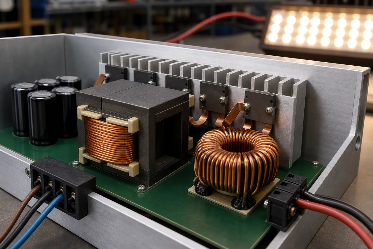
Representative product image. Confirm appearance and specifications with the manufacturer.

Product Specifications

Technical details and manufacturing context for Power Transformer/Inductor

Definition
The power transformer/inductor is a critical electromagnetic component used in LED driver circuits. It performs two primary functions: the transformer section steps up or steps down AC voltage levels to match the requirements of the LED array, while the inductor section stores energy in magnetic fields to regulate current flow, filter noise, and maintain stable power delivery. This component is essential for ensuring efficient and reliable operation of LED lighting systems.

Operating on the principle of electromagnetic induction, the transformer utilizes a primary winding and a secondary winding wound around a common magnetic core. When alternating current flows through the primary winding, it creates a changing magnetic field that induces a voltage in the secondary winding, thereby transforming voltage levels. As an inductor, it resists changes in current by storing energy in its magnetic field when current increases and releasing it when current decreases, which smooths current flow and reduces ripple.

Key parameters for selection include rated power (5–300 W), primary inductance (0.5–10 mH), leakage inductance (1–5%), DC resistance (0.05–2 Ω), isolation voltage (1500–4000 V AC, per IEC 61558), operating frequency (50–500 kHz), operating temperature (-40 to 125 °C), temperature rise (≤40 K, per IEC 60085), core material (e.g., PC40–PC95), wire material (Cu–Al), weight (10–500 g), and footprint (10×10×5 to 50×50×30 mm). These values are reference ranges and must be verified for the specific model and application.

Materials typically include ferrite cores, copper wire, insulation materials, and bobbins. The component is designed for surface-mount or through-hole mounting, depending on the footprint. It is used in various LED driver topologies, such as flyback converters, where the primary inductance is critical for energy storage.

When selecting this component, engineers must consider the electrical requirements, thermal constraints, and mechanical fit. Verification questions include: What is the required isolation voltage? What is the maximum operating temperature? What are the acceptable leakage inductance and DCR values? Maintenance signals include increased temperature rise, audible noise, or reduced efficiency, which may indicate core saturation or winding degradation. Failure boundaries include exceeding the rated isolation voltage, operating beyond the temperature range, or mechanical stress causing core fracture.

Always confirm model-specific values and standards with the legal manufacturer or supplier before procurement.
Working Principle
The power transformer/inductor operates on electromagnetic induction. When alternating current flows through the primary winding, it generates a changing magnetic field in the core. This field induces a voltage in the secondary winding, enabling voltage transformation. As an inductor, it stores energy in its magnetic field when current increases and releases it when current decreases, thereby smoothing current flow and filtering noise. The core material and winding configuration determine the inductance and saturation characteristics.
Common Materials
Ferrite Core, Copper Wire, Insulation Material, Bobbin
Technical Parameters
ParameterTypical rangeNotes & selection driver
Rated Power5–300 WDetermines transformer size and cost.
Primary Inductance0.5–10 mHCritical for energy storage in flyback converters.
Leakage Inductance1–5 %Lower leakage improves efficiency and reduces EMI.
DC Resistance (DCR)0.05–2 ΩAffects copper loss and temperature rise.
Isolation Voltage1500–4000 V ACEnsures safety isolation between primary and secondary.IEC 61558
Operating Frequency50–500 kHzHigher frequency reduces size but increases core loss.
Operating Temperature-40–125 °CExceeding range may degrade insulation and core properties.
Temperature Rise≤40 KLimits thermal stress on insulation and solder joints.IEC 60085
Core MaterialPC40–PC95Higher permeability reduces size but increases cost.
Wire MaterialCu–AlCopper offers lower resistance; aluminum is cheaper.
Weight10–500 gAffects mounting and mechanical design.
Footprint (L×W×H)10×10×5–50×50×30 mmMust fit PCB layout and enclosure.

Ranges are indicative industry figures for RFQ preparation, not a supplier commitment. Confirm every value and standard with the legal manufacturer before ordering.

Components / BOM
  • Magnetic Core Part
    Provides a path for magnetic flux and determines inductance value
    Material: Ferrite
  • Primary Winding Part
    Receives input power and creates magnetic field
    Material: Copper
  • Secondary Winding Part
    Delivers transformed output power to LED circuit
    Material: Copper
  • Bobbin Part
    Insulating structure that holds windings in place
    Material: Plastic
  • Insulation Layer Part
    Prevents electrical shorts between windings and core
    Material: Polyester Film

Applied To / Applications

This component is essential for the following industrial systems and equipment:

Industrial Ecosystem & Supply Chain Structure

Complementary Systems
Downstream Applications
Specialized Tooling

Application Fit & Sizing Matrix

Operational Limits
pressure: Atmospheric to 1.5 bar (sealed designs)
other spec: Frequency range: 20kHz to 500kHz, insulation class: H (180°C)
temperature: -40°C to +125°C (ambient), core temperature up to +150°C
Media Compatibility
✓ LED driver circuits ✓ Switch-mode power supplies ✓ Power factor correction circuits
Unsuitable: High-vibration industrial environments without additional mounting/securing
Sizing Data Required
  • Input/output voltage specifications
  • Required power rating (watts/VA)
  • Operating frequency range

Reliability & Engineering Risk Analysis

Failure Mode & Root Cause
Insulation breakdown
Cause: Thermal aging, moisture ingress, or electrical overstress degrading dielectric properties
Winding deformation or short circuit
Cause: Mechanical stress from through-fault currents, loose connections, or manufacturing defects
Maintenance Indicators
  • Audible humming or buzzing that increases in intensity or changes pitch
  • Visible oil leaks, discoloration, or bulging of the transformer tank
Engineering Tips
  • Implement regular dissolved gas analysis (DGA) to detect incipient faults in oil-filled transformers
  • Maintain proper cooling system operation and monitor top oil temperature to prevent thermal degradation

Indicative industry ranges for design and RFQ preparation. Confirm the exact figures and applicable standard with the manufacturer before specifying.

Compliance & Manufacturing Standards

Applicable Standards
ANSI C57.12.00 - Standard for General Requirements for Liquid-Immersed Distribution, Power, and Regulating Transformers CE Marking - Compliance with EU Directives (e.g., Low Voltage Directive 2014/35/EU)

Quoted from the published standard.

Manufacturing Precision
  • Winding Resistance: +/-2% of rated value
  • Insulation Resistance: Minimum 1000 MΩ at 20°C
Quality Inspection
  • Impulse Voltage Test (Lightning Surge Test)
  • Temperature Rise Test (Thermal Performance Test)

Manufacturers of Power Transformer/Inductor

Manufacturer profiles associated with Power Transformer/Inductor.

Sourcing Power Transformer/Inductor from China?
Tell us your specification and target quantity — we will match it against manufacturer records and come back with the factories that fit.
Request manufacturers We manufacture this

Manufacturer listings support early research and capability understanding. They are not certification, ranking, or transaction guarantees.

Technical documentation
Request current drawings, revision history, and a signed specification sheet.
Manufacturing capability
Verify equipment lists, process limits, capacity, and representative production evidence.
Inspection readiness
Confirm test methods, calibrated equipment, sampling plans, and traceable reports.
Supplier transparency
Check the legal entity, factory address, ownership, certifications, and direct contacts.

CNFX does not score or rank suppliers. Buyers must verify all claims and documents with the legal manufacturer before ordering.

Supply Chain Compatible Machinery & Devices

Medium Voltage Switchgear Assembly Line

Automated production system for assembling medium voltage electrical switchgear.

Explore Specs →
Motor Terminal Block

A motor terminal block is a standardized electrical component that provides secure, insulated connection points for motor winding leads.

Explore Specs →
PLC Control System

A digital industrial computer control system that monitors inputs, makes decisions based on a custom program, and controls outputs to automate industrial processes.

Explore Specs →
Control Panel

A centralized interface for monitoring and controlling industrial equipment and processes

Explore Specs →

Frequently Asked Questions

What is the difference between the transformer and inductor functions in this component?

The transformer function uses two windings to step up or step down AC voltage via electromagnetic induction. The inductor function uses a single winding to store energy in a magnetic field and release it to smooth current flow, which is essential for regulating current in LED drivers.

What are the typical isolation voltage requirements for this component?

The isolation voltage is typically in the range of 1500 to 4000 V AC, as per IEC 61558. This ensures safety isolation between the primary and secondary circuits. The exact value depends on the application and must be verified with the manufacturer.

How does operating frequency affect the size and performance of the transformer/inductor?

Higher operating frequencies (50–500 kHz) allow for smaller core sizes and reduced component volume, but they also increase core losses. Lower frequencies require larger cores but may reduce core losses. The optimal frequency depends on the driver design and efficiency targets.

What maintenance signals indicate a failing transformer/inductor?

Signs of failure include excessive temperature rise, audible noise (e.g., buzzing), reduced efficiency, or increased output ripple. These may indicate core saturation, winding degradation, or insulation breakdown. If such symptoms occur, the component should be inspected and replaced if necessary.

Data Basis

Editorial classification, named public sources where available, and source-reviewed manufacturer records.

Preliminary Technical Classification
This page supports structured research, RFQ preparation, and supplier evaluation. It does not replace buyer-led supplier qualification, standards review, or technical approval.
Buyer enquiry

Request manufacturing insight for Power Transformer/Inductor

Ask for use case, specification boundaries, supplier type, and RFQ preparation information for this product.

Where it goes
Straight to the CNFX editorial desk, and to the manufacturer if this product is linked to a claimed profile. Nothing is broadcast to a supplier list.
Your details stay here
We do not sell or rent enquiry data, and we do not add you to a mailing list. Used only to answer this request.
No commission, no middleman
CNFX is a directory. We take no cut of any order and never negotiate on a supplier's behalf.
What we don't claim
A listing is not an endorsement. Qualify every supplier and verify every figure yourself before ordering.

Your business information is used only to process this request.

Thank you! Your message has been sent. We'll respond within 1–3 business days.
Sorry, we couldn't send your message. Please try again, or email us at contact@cnfx.com.

Need to Manufacture Power Transformer/Inductor?

Compare manufacturer profiles with relevant product and process capability.

Previous Product
Wire Tensioning System
Last Product
Get QuotesChat