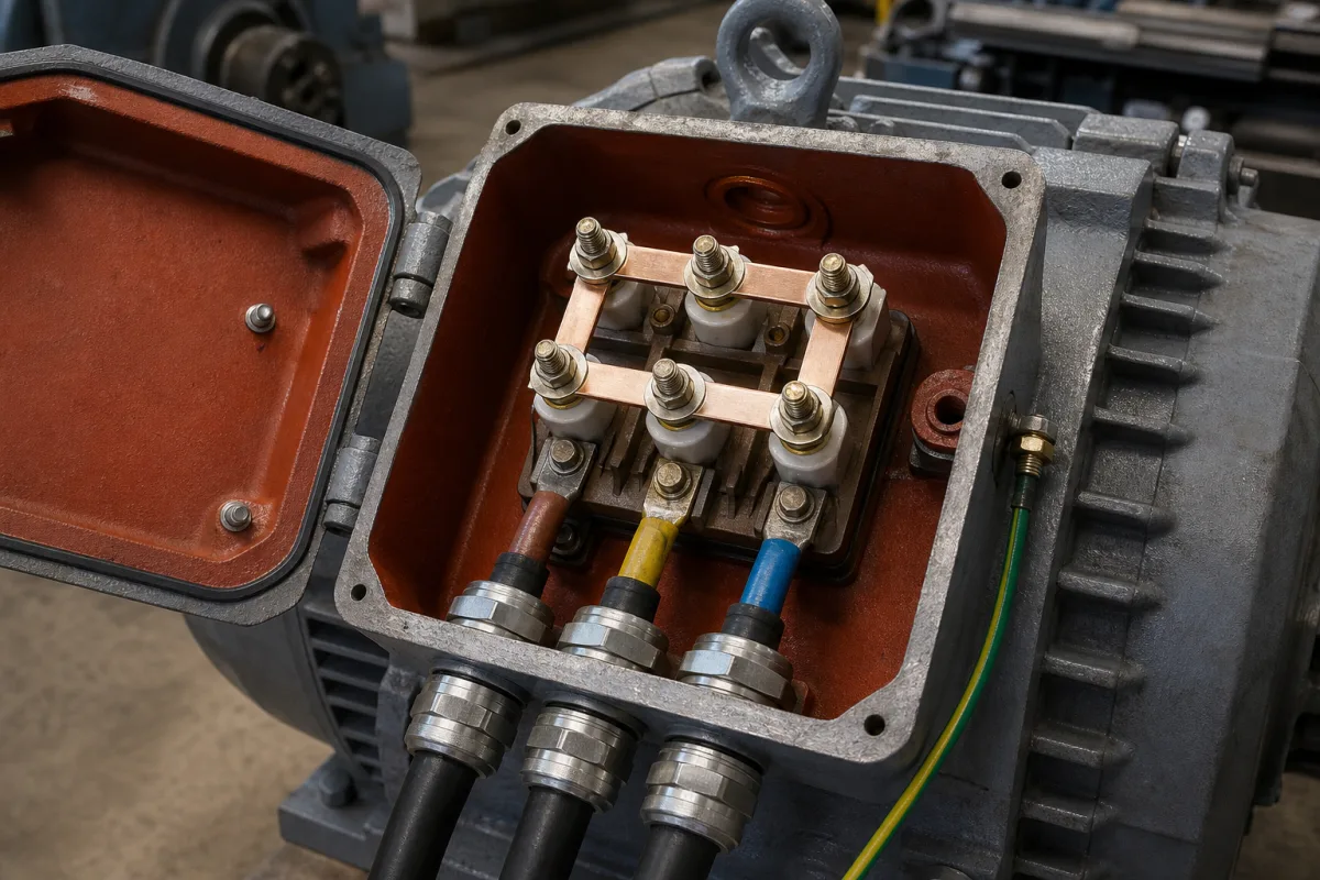
The motor terminal box as an enclosure: position, glands, Ex e
The terminal box in the illustration sits open on a cast motor frame: a hinged lid with its gasket, a six-stud terminal board with copper links inside, three supply cables entering through metal glands, and a separate green-and-yellow earth lead outside. The board and links decide how the motor is connected; the box around them decides whether the cable can reach it from the right side, whether water and dust stay out, and whether it can be used where gas may be present.
Covers the terminal box of electric motors as an enclosure: box position and cable entry direction, repositioning and its effect on sealing, gasket and cover fixing, cable gland selection by clamping range, tightening torque and pull-out force, IP ratings of glands, and the additional requirements for increased-safety (Ex e/eb) terminals inside boxes. The six-stud terminal board, studs and star/delta links are on Motor terminal board; complete motors are on Electric motor and Cast-iron TEFC IEC-frame three-phase motor; wall- and panel-mounted junction boxes, their enclosure ratings and Ex protection are on Electrical junction box; fibre-optic terminal boxes, overhead-line terminal boxes and heater terminal boxes are outside this page.
CNFX editorial research · Sources checked October 13, 2026 · 4 sources
SEW-EURODRIVE's service guide for its DR motors in frame sizes 71 to 132 shows how the box can be turned to suit the cable route.
The terminal box can sit in four positions, 0°, 90°, 180° and 270°, viewed from the fan guard, and the cable entry can face four directions, X, 1, 2 and 3, viewed on the box face; positions X and 2 swap when the box is at 180°. Moving the box means removing the fan guard and circlip, withdrawing the four tension rods, loosening the stator from the flange and rotating it, then re-tightening the rods in a diametrically opposed pattern. Changing the entry direction means removing the box, checking its gaskets, refitting it in the new orientation and making sure no wires are trapped in the seal.
SEW warns that doing this compromises the seal and paint applied at assembly and does not recommend it for washdown or corrosive installations. It is better to order the box position and entry direction with the motor.
Fastener (SEW DR71–DR132)
Tightening torque
Terminal box to frame screws
6.5 Nm (58 lb·in)
Terminal box lid screws
4 Nm (35 lb·in)
Fan guard screws
3.3 Nm (30 lb·in)
Tension rods
5, 9 or 21 Nm (45, 80 or 186 lb·in) depending on frame size
Give the box position and entry direction on the motor order, with the cable route drawing, rather than turning the box on site.
02
Cable glands: clamping range, torque and pull-out
A gland is chosen by the cable's outer diameter, not by the thread alone. Lapp's instruction sheet for its SKINTOP HEAT glands (IP 68 at 3 bar for 30 minutes, −20 to +200 °C dynamic) pairs each thread with a clamping range and a cap-nut torque. Lapp states that these torques are maximum values at normal climate, that lower torques must be used with some sheath materials to avoid damaging the sheath, and that a gland without a locknut may only be screwed into a threaded hole.
SEW-EURODRIVE's table for the EMC glands it supplies gives both the thread torque and the cable-clamping torque, and the cable pull-out force the gland must achieve. For an M25 brass or stainless gland, 7.0 Nm on the thread and 5.0 Nm on the clamp must hold a cable of 8 to 11 mm against 120 N, or 11 to 16 mm against 130 N; for an M16, 4.0 and 3.5 Nm hold a 4 to 8 mm cable against 75 N. SEW requires the cable fastening to reach the stated pull-out force and gives the clamping torque as the means to get there, so the pull-out force, not the torque, is the acceptance figure.
Thread
Lapp SKINTOP HEAT clamping range
Lapp cap-nut torque (max.)
SEW EMC gland: cable / pull-out
M16 × 1.5
6.0–9.5 mm
10 Nm
4–8 mm / 75 N
M20 × 1.5
8.0–12.0 mm
12 Nm
—
M25 × 1.5
12.0–16.0 mm
12 Nm
8–11 mm / 120 N; 11–16 mm / 130 N
M32 × 1.5
13.0–20.0 mm
18 Nm
—
M40 × 1.5
19.0–27.0 mm
18 Nm
—
M50 × 1.5
27.0–34.0 mm
20 Nm
—
Two makers' M25 glands clamp different ranges (12–16 mm against 8–16 mm), which is why the cable diameter has to be on the order. Ask for the gland type, clamping range, torques and IP rating for each entry.
03
Increased-safety terminals inside the box
Weidmüller's installation instructions for its WPD Ex eb power distribution blocks show the conditions that come with increased-safety terminals.
The terminals must be installed inside a suitable certified enclosure meeting IEC/EN 60079-0 and 60079-7 for gas (or 60079-31 for dust). All connections, including unused ones, must be tightened to the stated torques. Only one cable may go into each incoming connection; two wires in one connection point need twin-end ferrules crimped with the right tool, and multiple loose wires are not allowed. Where terminals are combined with other series or accessories, creepage and clearance distances must still be met, and if smaller conductors than rated are used, the lower current must be written into the certificate of the complete apparatus.
The permitted ambient temperature depends on the temperature class: up to 40 °C for T6, 55 °C for T5 and 60 °C for T4, against an insulating material limit of 100 °C.
WPD 107 (Ex eb)
Value
Rated voltage / current
440 V / 232 A (ΔT 40 K)
Contact resistance, 95 mm²
< 0.14 mΩ
Ambient for T6 / T5 / T4
up to 40 / 55 / 60 °C
Terminal screw torques
M6 2.5 Nm, M8 3.5 Nm, M12 14 Nm
These are one terminal maker's conditions; an Ex e motor terminal box carries its own certificate. Ask for the box's Ex marking, the certificate's schedule of limitations, and certified glands for every entry.
04
What to state for a motor terminal box
Paste it into your enquiry below or into an email to a maker, then replace every bracket.
Give the box position (0°, 90°, 180°, 270° from the fan side) and cable entry direction, the number of entries, each cable's outer diameter and type, required IP rating, ambient temperature and washdown or corrosive conditions, and whether the area is classified (zone, gas group, temperature class). Ask for gland types with clamping ranges and torques, box and lid gasket material, internal and external earth terminals, and for Ex areas the box certificate and certified glands.
3 companies list this product among what they make. Company figures are quoted from each
company's own website; every card states where the relationship came from.
CZ Electric Co., Ltd.
TBC
CZ's site lists Ex e cable terminal boxes and junction boxes in stainless steel, aluminium alloy and GRP, Ex d junction boxes and Ex cable glands; ask whether a motor-mounted version is offered.
Explore company information and manufacturing capabilities, then discuss the scope of your project with a relevant supplier.
Share this page
Compiled and source-reviewed by the CNFX editorial team.
Each manufacturer above links to the page on that company's own website where the product is listed, with the date we checked it. How we source and review
· Page last updated 13 October 2026
Buyer questions
Can the terminal box be turned after delivery?
On SEW's DR71–DR132 motors, yes, to 0°, 90°, 180° or 270°, but SEW warns it compromises the factory seal and paint and does not recommend it for washdown or corrosive sites. [1]
How is a cable gland sized?
By the cable's outer diameter: Lapp's M25 SKINTOP HEAT clamps 12–16 mm at up to 12 Nm, while SEW's M25 EMC gland covers 8–16 mm in two pull-out classes. [3][2]
What pull-out force must a gland hold?
SEW specifies 75 N for 4–8 mm cables in an M16 and 120–130 N for 8–16 mm cables in an M25 at the stated clamping torque. [2]
Can two wires share one Ex e terminal?
Weidmüller's WPD conditions allow one cable per incoming connection; two wires need twin-end ferrules, and multiple loose wires are not allowed. [4]
Sources and what still needs a direct check
Sources checked 2026-10-13. A geared-motor maker's service guide and tightening-torque table, a cable-gland maker's instruction sheet and a terminal maker's Ex installation conditions.