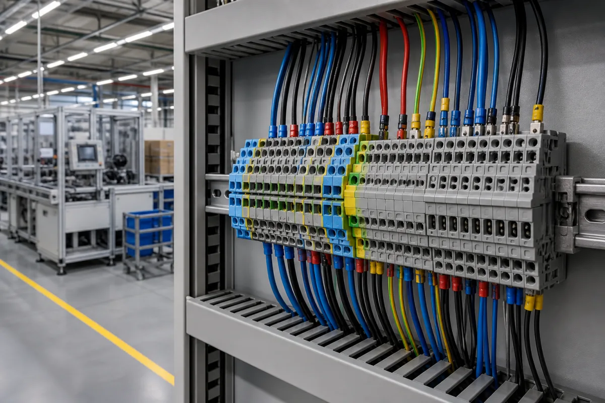
Control panels · Ratings, derating and insulation distances
A terminal block is a small part that carries a panel's whole current through a few square millimetres of contact. Check which standard the block is tested to, size it for the conductor and current at your cabinet temperature rather than at room temperature, and confirm the insulation voltage and distances suit your supply and pollution degree.
DIN-rail, PCB, pluggable and barrier terminal blocks with screw, spring and push-in clamping for copper conductors in control panels and equipment. Plug connectors and cable lugs are outside this page.
CNFX editorial research · Sources checked October 10, 2026 · 5 sources
IEC 60947-7-1 covers terminal blocks with screw-type or screwless clamping units for industrial use, fixed to a support, connecting round copper conductors from 0.2 mm² to 300 mm² (AWG 24 to 600 kcmil) in circuits up to 1,000 V AC (up to 1,000 Hz) or 1,500 V DC. Insulation-piercing and special component terminal blocks are outside its main scope. [1]
The 2009 edition was withdrawn on 15 April 2025 and replaced by a 2025 edition; ask suppliers which edition their test reports refer to. In North America, Phoenix Contact notes that UL 1059 applies, with its own temperature-rise and spacing rules. [1][2]
Ask for the rated cross-section and the range of conductor sizes and types (solid, stranded, with or without ferrules) each clamping point accepts, and the tightening torque for screw types.
Give the supplier the conductor sizes and types, current per circuit, voltage, mounting (DIN rail or PCB) and any certification needed in the market of use.
02
Derate current for cabinet temperature and neighbouring blocks
Phoenix Contact explains that a derating curve shows current-carrying capacity against ambient temperature and the number of neighbouring loaded contacts, and is affected by contact material and housing. For its pluggable blocks, the base curve is measured to DIN EN 60512-5-1 with a 100 °C insulation limit, and the permissible load current is 0.8 times the base current, for 2-, 5-, 10- and 15-position arrangements. [2]
In the IEC temperature-rise test it describes, five blocks on a rail are wired in series with conductors of the rated cross-section and carry that cross-section's rated current; at about 20 °C room temperature the middle block may rise by at most 45 K. UL 1059 uses three blocks at 25 °C and allows 30 K. [2]
As an editorial example only: a block that passes a 45 K rise at 20 °C reaches about 65 °C; assuming the same rise, the same current in a cabinet at 45 °C gives about 90 °C. Read the derating curve at your cabinet temperature and number of adjacent loaded blocks before choosing the size.
03
Look for low, stable contact resistance
Phoenix Contact notes that current transfer depends on the resistance between conductor and current bar, and that high-quality contacts create a gas-tight connection. Its voltage-drop test allows at most 3.2 mV per block, before and after testing, and no more than 1.5 times the starting value. [2]
For short-circuit withstand it describes testing protective-conductor blocks at 120 A/mm² of the rated cross-section in three 1-second stages, after which parts must be undamaged and pass the voltage-drop test. Ask for these test results for the series offered. [2]
04
Confirm insulation voltage, clearances and creepage
Phoenix Contact describes the dielectric test as 1,000 V plus twice the rated insulation voltage, with no sparkover and creepage current below 100 mA, and explains that minimum clearance depends on rated surge voltage, overvoltage category and pollution degree, while creepage depends on the RMS working voltage and insulation material group. [2]
IEC 60947-7-1 refers clearances and creepage distances to Annex H of IEC 60947-1; UL 1059 uses separate tables by use group and voltage. State the supply voltage, overvoltage category and pollution degree of the cabinet when asking for ratings. [1][2]
05
Compare what suppliers offer
Suppliers linked to this page list DIN-rail, PCB, pluggable, barrier, feed-through and transformer terminal blocks with screw, spring and push-in clamping. [3][4][5]
Degson lists pluggable, PCB, barrier, through-wall, transformer and feed-through blocks; Wanjie lists PCB screw, screwless, pluggable, spring and DIN-rail blocks; CNC Electric lists UK-series and push-in DIN-rail terminal blocks. [3][4][5]
06
Trace the terminal block components
This is a functional reference built from the sources cited; it is not one maker's parts list.
Part
Role
Fix in the order
Current bar
Carries current between clamping points; contact quality sets resistance. [2]
Material, plating and rated current.
Clamping unit
Screw, spring or push-in connection to the conductor. [1]
Clamping type, conductor range and torque.
Insulating housing
Sets temperature limit and insulation distances. [2]
Material, temperature class and flammability rating.
Fill the specification fields with values for your panel
A terminal block quotation needs panel-specific values. The table explains each field, gives published values where a reviewed source states them, and says what to obtain from the supplier.
Field
What it means and published values
Ask the supplier for
Rated current (A)
Tested at the rated cross-section's current; derate for ambient. [2]
Rated current and derating curve.
Rated voltage (V AC)
IEC 60947-7-1 covers up to 1,000 V AC or 1,500 V DC. [1]
Rated and insulation voltage.
Insulation resistance (MΩ)
Insulation quality.
Insulation resistance.
Dielectric strength (kV)
Test voltage 1,000 V + 2 × Ui, as described by Phoenix Contact. [2]
Dielectric test voltage.
Contact resistance (mΩ)
Voltage drop limited to 3.2 mV per block in the test described. [2]
Voltage-drop test result.
Operating temperature (°C)
Housing limit; Phoenix Contact cites 100 °C for its base curve. [2]
Send the conductor, current and panel data together
Paste it into your enquiry below or into an email to a maker, then replace every bracket.
Circuits: [conductor size and type; ferrules; current per circuit; voltage]
Panel: [ambient temperature in cabinet; number of adjacent loaded blocks; overvoltage category; pollution degree]
Type: [DIN rail or PCB; screw, spring or push-in; pluggable; fuse, disconnect or earth blocks]
Standards: [IEC 60947-7-1 edition; UL 1059; other approvals]
Accessories: [end plates; jumpers; markers]
Documents: [derating curves; temperature-rise, voltage-drop and dielectric test reports; certificates]
Explore company information and manufacturing capabilities, then discuss the scope of your project with a relevant supplier.
Share this page
Compiled and source-reviewed by the CNFX editorial team.
Published product pages show what a company offers, not tested performance. Confirm the legal seller, factory and scope for your order. How we source and review
· Page last updated 13 October 2026
Buyer questions
Which standard covers industrial terminal blocks?
IEC 60947-7-1 covers screw and screwless terminal blocks for copper conductors from 0.2 to 300 mm² up to 1,000 V AC or 1,500 V DC; its 2009 edition was replaced in 2025. UL 1059 applies in North America. [1][2]
How hot can a terminal block get at rated current?
Phoenix Contact describes the IEC test as allowing at most a 45 K rise at about 20 °C room temperature; UL 1059 allows 30 K at 25 °C. [2]
Why derate terminal block current?
Phoenix Contact explains that current-carrying capacity falls with ambient temperature and with more neighbouring loaded contacts, as shown by the derating curve. [2]
Sources and what still needs a direct check
Sources checked 2026-10-10. The IEC webstore abstract gives the scope of IEC 60947-7-1. Phoenix Contact, a terminal block manufacturer, describes the IEC and UL tests; its figures for its own products are not limits for others. Supplier pages describe their own offers. The full IEC 60947-7-1, IEC 60947-1 and UL 1059 texts were not read for this page.