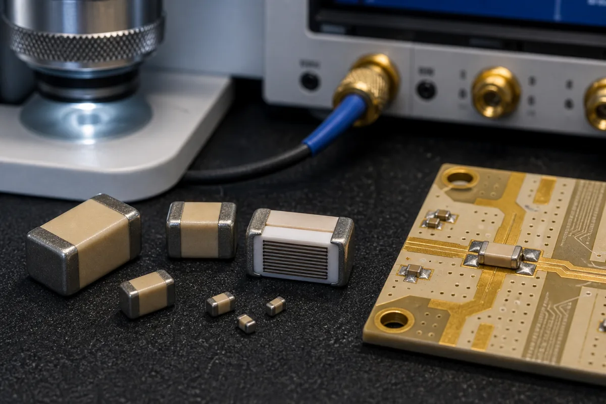
RF and microwave MLCCs · ESR, Q and dissipation factor at the design frequency, series and parallel resonance, mounting orientation, C0G stability
A high-frequency or high-Q multilayer ceramic capacitor (MLCC) is a chip capacitor built from a low-loss, temperature-stable ceramic (such as NP0/C0G) with low-resistance electrodes, used for coupling, bypass, matching and tuning in RF and microwave circuits. Ask three things first: what ESR and Q it has at your design frequency, where its series and parallel resonances fall when mounted on your board, and how stable its capacitance is with temperature.
Surface-mount multilayer and single-layer ceramic capacitors for RF and microwave circuits. General-purpose X7R/X5R MLCCs, high-voltage disc and plate capacitors, RF power capacitors for transmitters and tantalum or film capacitors are outside this page.
CNFX editorial research · Sources checked October 11, 2026 · 4 sources
Check ESR, Q and dissipation factor at your frequency
KYOCERA AVX's technical note on selecting RF chip capacitors explains that equivalent series resistance (ESR) comes from dielectric losses and from metal losses in electrodes and terminations: at Hz–kHz dielectric loss dominates, but at RF metal losses dominate and, through skin effect, rise with the square root of frequency. The note says ESR is given in milliohms at specific frequencies, measured between 30 MHz and 1 GHz under guidelines such as EIA RS-483 and MIL-C-55681, so an ESR specified at 150 MHz should be multiplied by √(900/150) for a 900 MHz design. [1]
The note defines Q = Xc/ESR and dissipation factor DF = 1/Q = ESR/Xc; power lost is P = I² × ESR. It cites the company's 100 Series porcelain capacitors with a loss tangent below 0.0001, giving Q above 10,000 and losses below 0.01%. [1]
Editorial calculation with these relations: a capacitor with 0.05 Ω ESR at 150 MHz has about 0.05 × √6 ≈ 0.12 Ω at 900 MHz; a 10 pF part has Xc = 1/(2π × 900 MHz × 10 pF) ≈ 17.7 Ω there, so Q ≈ 17.7/0.12 ≈ 145. The ESR value is an assumed example, not a datasheet figure. [1]
Johanson Technology's C-Series high-Q MLCCs use copper electrodes instead of palladium and silver, exhibit NP0 (C0G) temperature characteristics, and are offered in 0402, 0603 and 0805 sizes with ESR enhanced above 1.5 GHz. [2]
Give the supplier the frequency band, circuit function (coupling, bypass, matching, tuning), capacitance and tolerance, voltage and RF current, case size and land pattern, substrate and mounting orientation, temperature range, the ESR or Q required at the design frequency, and whether S-parameter files are needed.
02
Ask how the electrode stack keeps ESR low at high frequency
Murata's US patent 5,040,092 (priority 20 July 1989, granted 13 August 1991) explains why simply thickening the internal electrodes or doubling them does not fix RF loss: such structures lower ESR at direct current, but eddy-current loss keeps ESR high in a band the patent puts at tens of megahertz up into the gigahertz range, so Q there is not improved. [3]
Its remedy splits the internal electrodes into two or more groups separated by a thicker ceramic layer of thickness a, at least twice the layer thickness b between electrodes within a group (a ≥ 2b), which reduces eddy-current loss between the groups. In the measured example b was 20 µm and a was 300 µm, compared against a = 20 µm; the patent reports ESR at 1 GHz falling as a was increased from 20 to 300 µm, little benefit when a was between b and 2b, and Q improved by approximately 25% over a conventional capacitor with the same number of electrodes. The upper limit on a is set by the capacitor's size. [3]
Editorial calculation: with Q = Xc/ESR from the KYOCERA AVX note, a 25% higher Q at the same capacitance and frequency means ESR about 1/1.25 = 0.8 times, a 20% reduction — on the 10 pF, 900 MHz example above, from about 0.12 Ω to about 0.10 Ω, raising Q from about 145 to about 181. Electrode material is a second lever: Johanson's C-Series uses copper electrodes. Ask suppliers for measured ESR or Q curves across your band rather than a single-frequency figure. [3][1][2]
03
Check series and parallel resonance and mounting
KYOCERA AVX models chip capacitors with lumped elements that give the series resonant frequency and equivalent series inductance, and specifies S-parameters for its parts. The series resonance occurs at 0° phase of S21, where S21 shows minimum loss equal to the ESR; parallel resonances show as sharp dips in S21 magnitude. If a parallel resonance falls in the band of interest, a coupling capacitor attenuates the RF energy instead of passing it. [1]
The note explains that mounting a chip capacitor vertically, with its electrodes perpendicular to the microstrip, removes the first parallel resonance and significantly extends the usable passband, and that capacitance can be checked at the S21 3 dB frequency using C = 0.159/(100 × F). [1]
Editorial note: resonances depend on case size, orientation, pad layout and substrate, so ask for S-parameter (S2P) files measured in a fixture close to your layout, and verify on your board.
04
High-Q chip capacitors and RF power capacitors among the listed makers
Fujian Torch's reviewed page is a high-Q multilayer chip capacitor range; Cixi Anxon's is an RF power ceramic capacitor range.
Listings range from high-Q multilayer chip capacitors to RF power plate capacitors; ask each for ESR or Q curves, self-resonant frequency, S-parameter files and the dielectric class.
05
Match case size to capacitance and working voltage
Passive Plus's High-Q / Low ESR range page lists its C-Series (NP0, 0±30 PPM/°C) and P-Series (P90, +90±20 PPM/°C) multilayer ceramic capacitors as High-Q (>10,000) parts for UHF/microwave power amplifiers, mixers, oscillators, filter networks and low-noise amplifiers, designed and manufactured to meet MIL-PRF-55681 and MIL-PRF-123, with magnetic or non-magnetic terminations. [4]
The page says the N-Series EIA-size capacitors (NP0, 0±30 PPM/°C) were developed for High-Q and microwave uses needing low noise, high self-resonance and high working voltage, and it offers S-parameter data in horizontal or vertical mounting orientation depending on case size. [4]
Editorial note: case size, capacitance and working voltage are linked in this table; the largest 0402N value listed is 33 pF at 250 WVDC, while 1111C/P reaches 10,000 pF at 500 WVDC. State all three, and the mounting orientation of any S-parameter file, in the enquiry.
Datasheet entries to request, from DF and self-resonance to termination finish
Insulation resistance, withstanding voltage, aging rate and chip weight have no published value in the reviewed sources, so take them from the candidate part's datasheet.
Explore company information and manufacturing capabilities, then discuss the scope of your project with a relevant supplier.
Share this page
Compiled and source-reviewed by the CNFX editorial team.
Each manufacturer above links to the page on that company's own website where the product is listed, with the date we checked it. How we source and review
· Page last updated 13 October 2026
Buyer questions
How does ESR of an RF capacitor change with frequency?
KYOCERA AVX notes RF ESR is dominated by metal losses that rise with the square root of frequency, so scale a 150 MHz value by √(f/150 MHz). [1]
KYOCERA AVX says vertical mounting removes the first parallel resonance and extends the usable passband. [1]
Why don't thicker electrodes always raise Q at RF?
Murata's US patent 5,040,092 notes that thicker or doubled electrodes lower DC ESR but eddy-current loss keeps ESR high from tens of MHz to GHz; separating electrode groups by a layer at least twice as thick raised Q by about 25%. [3]
What working voltage do high-Q RF chip capacitors have?
It depends on case size: Passive Plus lists 250 WVDC for its 0402N and 0603N parts, 500/1,500 WVDC for 1111C/P and 3,600/7,200 WVDC for 3838C/P. [4]
Sources and what still needs a direct check
Sources checked 2026-10-11. KYOCERA AVX and Johanson are RF capacitor makers describing their own products and design practice; Murata's patent describes its own electrode-stack design and test results. Values for another capacitor must come from its datasheet and S-parameter files.