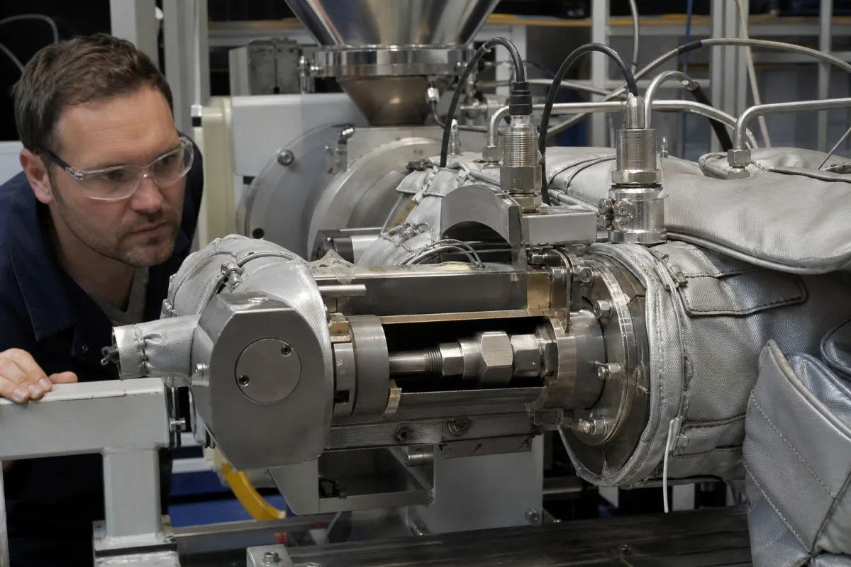
Melt flow control element: the adjustable throttle valve that sets back pressure between an extruder and its die
The adjustable throttle between an extruder screw and its die · plunger and land geometry for a linear pressure drop, motor-driven valves on a melt-pressure loop, the transducer that reads it, and start-up valve/throttle slides
A single-screw or twin-screw extruder can only build the pressure that the restriction in front of it demands. Fitting an adjustable throttle in the adapter between the barrel and the die lets the operator raise that back pressure — to influence melting and reach a higher melt temperature — without changing the screw or the die. This page is about that flow control element: how its geometry sets the way pressure drop responds to stem travel, how it is driven and closed round a melt-pressure signal, and how it is combined with the start-up valve.
Adjustable flow control elements in the melt path of plastics and food extruders: plunger, needle and slide throttles that set back pressure, their drives and melt-pressure control loops, the melt pressure transducers they use, and combined start-up valve/throttle units. Hygienic diaphragm valves for dairy and beverage lines are covered on the Sanitary diaphragm valve for dairy processing page and hygienic angle-seat control valves with plug and seat trims on the Sanitary flow control valve page; complete extruders and dies are outside this page.
CNFX editorial research · Sources checked October 12, 2026 · 5 sources
A pressure drop that rises in step with stem travel: plunger clearance and land length
US patent 3,647,344 (Monsanto, filed 1970) describes a back-pressure valve for molten thermoplastic in which a plunger slides from a wide section of the flow channel into a narrow section of constant bore. The clearance between plunger and wall stays constant, so the pressure drop across the valve is substantially proportional to how far the plunger lies inside the narrow section — the land length. [1]
The patent contrasts this with a standard pressure control valve, whose pressure drop changes exponentially with stem position: its graph rises steeply once the stem passes 0.3 inch, and the patent states that small changes in pressure drop are extremely difficult to control with the standard valve once the drop exceeds 400 psi. Clearance and land length together set the operating range — for a large drop over a short land, the clearance must be reduced. [1] It adds that the linear relation can drift if the melt changes temperature through the valve. [1]
Editorial calculation: 400 psi is about 27.6 bar. On a valve whose drop follows the land length linearly, each millimetre of stem travel adds the same increment of back pressure, so a positioner's resolution translates directly into a pressure step; on a valve whose drop rises exponentially, a millimetre near closure adds a larger increment than a millimetre near full opening.
Dimension for molten thermoplastic (patent's preferred range)
Give the valve maker the polymer and melt flow index, the throughput range, the back pressure wanted above the die pressure, the melt temperature, and the stem resolution of the drive.
02
Motor-driven throttles on a melt-pressure loop, and what a fully open valve tells you about the screen
US patent 3,819,292 (Beloit, filed 1972) builds the throttle into a housing with a screen and breaker plate: the inlet passage ends in a tapered seat, a tapered metering element moves in and out of it through a geared drive from a reversible motor, and a pressure transducer in the inlet passage drives the motor so the extruder holds a programmed pressure. [2]
Nordson's EDI PolyStream assembly for extrusion coating and laminating applies the same principle between extruder and die: a drive opens the valve to varying degrees from a controller fed continuously by a pressure transducer, to hold back pressure within a target range — Nordson notes that extrusion coating needs a back-pressure valve to reach its higher melt temperatures, but that excess back pressure can degrade the polymer. When the valve reaches its opening limit because contamination has built up on the filtration screen, the system warns that the screen should be changed. The assembly comprises a motor, breaker-plate screen pack, linear valve, melt pipe, controls and an optional display. [4]
Editorial note: because the screen pack and the throttle sit in series, a closed-loop throttle hides a clogging screen by opening further; the valve position is therefore a screen-condition signal, and the control system should record it.
Ask whether the throttle is manual or motorised, how the position is measured, which pressure (before or after the screen) it controls, and what alarm it gives at full opening.
03
Reading the melt pressure the throttle controls: a 0–10,000 psi transducer at 400 °C
The control signal comes from a melt pressure transducer threaded into the adapter upstream of the throttle. A distributor's specification for the Dynisco PT460E-10M-6, a rigid-stem unit with a 6 in (15 cm) snout and a 1/2-20 UNF thread, gives these values. [5]
Editorial calculation: ±0.5% of a 10,000 psi span is ±50 psi (about ±3.4 bar), and at ±1.0% it would be ±100 psi; that uncertainty is a quarter of the 400 psi drop above which the Monsanto patent says a standard valve becomes hard to control. Choose the transducer span close to the working pressure, since the error is a percentage of full scale, and ask the supplier which accuracy figure applies to the unit quoted. [5][1]
Start-up valve and throttle in one slide across the discharge channel
US patent 4,984,977 (Werner & Pfleiderer, filed 1988) addresses screw extruders that need both a start-up valve, to divert material while the machine comes up to condition, and a throttle to generate back pressure on the melt. To avoid long melt paths through two separate units, it combines them in one starting-valve/throttle body that slides at right angles to the conveying direction from a start-up position into a throttling position. [3]
The patent names shear- and dwell-time-sensitive materials — commercial plastics and food compounds — as the reason for throttling at the end of the machine, to influence melting or plasticising and the material temperature before discharge. [3] Editorial note: on a compounding line, ask whether the throttle and start-up diverter are one unit or two, and the melt volume each adds between screw tip and die, since that volume is where sensitive material degrades.
05
What to send for an extruder flow control element
Paste it into your enquiry below or into an email to a maker, then replace every bracket.
Extruder: [single or twin screw; screw diameter; output range]
Material: [polymer or food compound; MFI or viscosity; melt temperature]
Pressure: [die pressure; back pressure wanted; maximum]
Valve: [plunger, needle or slide; manual or motorised; stroke and resolution]
Loop: [transducer range and position; controller; screen-change alarm]
Start-up: [diverter needed; combined unit]
Connection: [adapter flange; heating; insulation]
Explore company information and manufacturing capabilities, then discuss the scope of your project with a relevant supplier.
Share this page
Compiled and source-reviewed by the CNFX editorial team.
Each manufacturer above links to the page on that company's own website where the product is listed, with the date we checked it. How we source and review
· Page last updated 13 October 2026
Buyer questions
What does a throttle valve between an extruder and its die do?
It raises back pressure on the melt; Werner & Pfleiderer's patent uses it to influence melting and material temperature, and Nordson's extrusion-coating valve holds back pressure in a target range. [3][4]
Why use a plunger valve with a constant clearance?
Monsanto's patent says its pressure drop is proportional to stem position, while a standard valve changes exponentially and is hard to control above 400 psi of drop. [1]
How is the throttle controlled automatically?
Beloit's patent moves a tapered valve element with a reversible motor driven by an inlet pressure transducer; Nordson's PolyStream uses closed-loop control and warns when the valve is fully open because the screen is clogging. [2][4]
What range and accuracy does a melt pressure transducer have?
A Dynisco PT460E-10M-6 listing gives 0–10,000 psi, ±0.5% FSO combined error (also described there as ±1.0%), ±0.2% repeatability and 400 °C diaphragm temperature. [5]
Sources and what still needs a direct check
Sources checked 2026-10-12. Valve geometry and the 400 psi control limit come from a Monsanto patent; motor-driven throttles from a Beloit patent and Nordson's PolyStream announcement; the combined start-up valve/throttle from a Werner & Pfleiderer patent; transducer data from a distributor's PT460E-10M-6 specification.