Editorial Technical Reference

Load Sensor

This page explains how Load Sensor is classified within Machinery and Equipment Manufacturing. Technical values and manufacturer relationships are research references; confirm the current specification and supplier evidence for each order.

Technical Definition & Core Assembly

A transducer that converts mechanical load or force into an electrical signal for measurement and monitoring.
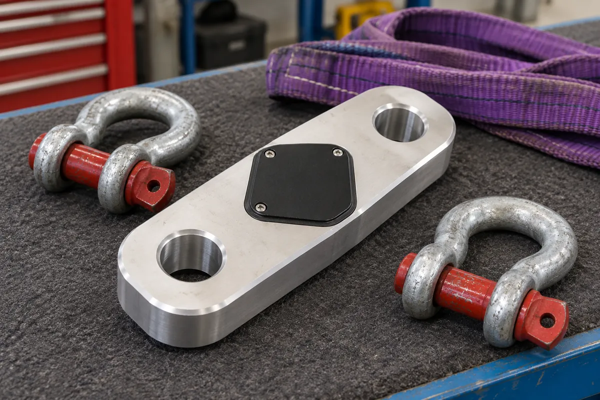
Representative product image. Confirm appearance and specifications with the manufacturer.

Product Specifications

Technical details and manufacturing context for Load Sensor

Definition
A load sensor is a component used in machinery and equipment manufacturing to measure the force or load applied to a structure. It is commonly integrated into Load Moment Indicator (LMI) systems for cranes, hoists, and other lifting devices. The sensor converts mechanical deformation caused by the load into an electrical signal, which is then processed to calculate load moment and prevent overload conditions. This real-time data is essential for safe operation and compliance with operational limits.

The sensor typically employs strain gauge technology. A sensing element, often made of stainless steel or aluminum alloy, deforms under load, and strain gauge foils attached to it change electrical resistance proportionally. This resistance change is converted into a voltage or current signal, which is transmitted to a processing unit.

Key parameters include rated capacity (0.5–100 t), accuracy class (0.05–0.5 %FS per OIML R60), nonlinearity (±0.03–±0.1 %FS), hysteresis (±0.02–±0.05 %FS), repeatability (±0.01–±0.03 %FS), rated output (1.0–3.0 mV/V), excitation voltage (5–12 V DC), input/output resistance (350–700 Ω), insulation resistance (≥5000 MΩ at 50 V DC), compensated temperature range (-10 to 40 °C), operating temperature range (-20 to 70 °C), temperature effects on zero and span (±0.02–±0.05 %FS/10°C), safe overload (120–150 %FS), ultimate overload (200–300 %FS), IP rating (IP65–IP68 per IEC 60529), material (17-4PH stainless steel per ASTM A693), and cable length (3–12 m).

These values are typical ranges for directory reference; actual specifications must be confirmed with the manufacturer for the specific model and application. The sensor is designed for use in industrial environments, with dust-tight and water-resistant enclosures. It is not a standalone safety device; it must be integrated into a complete LMI system and properly calibrated. Regular verification of accuracy and functionality is recommended to ensure reliable operation.
Working Principle
The load sensor operates on the principle of strain gauge technology. When a load is applied, a sensing element (typically a metallic body) deforms elastically. Strain gauge foils bonded to the element experience a change in electrical resistance proportional to the strain. This resistance change is measured using a Wheatstone bridge configuration, which converts the small resistance variations into a measurable voltage or current signal. The signal is then amplified and conditioned to provide an output proportional to the applied load. The sensor is designed to operate within specified temperature and overload limits to maintain accuracy and prevent damage.
Common Materials
Stainless steel, Aluminum alloy, Strain gauge foil
Technical Parameters
ParameterTypical rangeNotes & selection driver
Rated Capacity0.5–100 tSelect based on maximum expected load
Accuracy Class0.05–0.5 %FSHigher accuracy for precision weighingOIML R60
Nonlinearity±0.03–±0.1 %FSDeviation from ideal straight line
Hysteresis±0.02–±0.05 %FSDifference between loading and unloading
Repeatability±0.01–±0.03 %FSConsistency of output under repeated loads
Rated Output1.0–3.0 mV/VSignal at rated capacity
Excitation Voltage5–12 V DCRecommended supply voltage range
Input Resistance350–700 ΩBridge input impedance
Output Resistance350–700 ΩBridge output impedance
Insulation Resistance≥5000 At 50 V DC
Compensated Temperature Range-10–40 °CWithin this range, specifications hold
Operating Temperature Range-20–70 °CExtended range may affect accuracy
Temperature Effect on Zero±0.02–±0.05 %FS/10°CChange in zero per 10°C
Temperature Effect on Span±0.02–±0.05 %FS/10°CChange in output per 10°C
Safe Overload120–150 %FSMaximum load without permanent damage
Ultimate Overload200–300 %FSMaximum load before structural failure
IP RatingIP65–IP68Dust-tight and water-resistantIEC 60529
Material17-4PHStainless steel for corrosion resistanceASTM A693
Cable Length3–12 mCustom lengths available

Ranges are indicative industry figures for RFQ preparation, not a supplier commitment. Confirm every value and standard with the legal manufacturer before ordering.

Components / BOM
  • Strain Gauge Part
    Converts mechanical strain into electrical resistance change
    Material: Constantan or Nichrome foil
  • Elastic Element Part
    Deforms under applied load to transfer force to strain gauges
    Material: Stainless steel or aluminum
  • Protective Housing
    Shields internal components from environmental damage
    Material: Stainless steel or IP-rated plastic
  • Cable/Connector Part
    Transmits electrical signals to LMI processing unit
    Material: Shielded copper cable with weatherproof connector

Industry Taxonomies & Aliases

Commonly used trade names and technical identifiers for Load Sensor.

Applied To / Applications

This component is essential for the following industrial systems and equipment:

Industrial Ecosystem & Supply Chain Structure

Complementary Systems
Downstream Applications
Specialized Tooling

Application Fit & Sizing Matrix

Operational Limits
pressure: Up to 150% of rated capacity (overload), 200% of rated capacity (ultimate)
other spec: Humidity: 0-95% RH non-condensing, IP67/IP68 protection, Accuracy: ±0.1% to ±0.5% FS
temperature: -40°C to +85°C (operating), -55°C to +125°C (storage)
Media Compatibility
✓ Steel/Alloy contact surfaces ✓ Hydraulic fluids (mineral-based) ✓ Industrial lubricants
Unsuitable: Chlorinated solvents or highly corrosive chemical environments
Sizing Data Required
  • Maximum expected load (force range in N/lbf)
  • Required accuracy and resolution (%FS)
  • Mounting configuration and space constraints

Reliability & Engineering Risk Analysis

Failure Mode & Root Cause
Signal Drift/Calibration Loss
Cause: Thermal cycling, mechanical stress, or aging of internal components (e.g., strain gauges, amplifiers) leading to inaccurate load readings over time.
Electrical Overload/Short Circuit
Cause: Exposure to moisture, corrosive environments, or voltage spikes damaging circuitry, insulation, or sensor elements.
Maintenance Indicators
  • Inconsistent or erratic load readings compared to expected values
  • Visible physical damage (cracks, corrosion) or audible electrical noise/buzzing from the sensor
Engineering Tips
  • Implement regular calibration checks and environmental protection (e.g., sealing, temperature control) to maintain accuracy.
  • Use surge protection devices and ensure proper electrical grounding to prevent overload damage.

Indicative industry ranges for design and RFQ preparation. Confirm the exact figures and applicable standard with the manufacturer before specifying.

Compliance & Manufacturing Standards

Applicable Standards
ISO 376:2011 (Calibration of force-proving instruments used for the verification of uniaxial testing machines) ASTM E74-18 (Standard Practice of Calibration of Force-Measuring Instruments for Verifying the Force Indication of Testing Machines)

Quoted from the published standard.

Manufacturing Precision
  • Non-linearity: ≤±0.05% of full scale output
  • Creep (30 minutes): ≤±0.03% of applied load
Quality Inspection
  • Calibration Verification against a traceable master load cell (per ISO 376)
  • Electrical Safety Test (insulation resistance, dielectric strength) per IEC 61010-1

Manufacturers of Load Sensor

1 company lists this product among what they make. Company figures are quoted from each company's own website; every card states where the relationship came from.

HaiboSensor
Guangdong, CN
Listed on the company's own website · profile compiled by CNFX from public sources

Manufacturer listings support early research and capability understanding. They are not certification, ranking, or transaction guarantees.

Technical documentation
Request current drawings, revision history, and a signed specification sheet.
Manufacturing capability
Verify equipment lists, process limits, capacity, and representative production evidence.
Inspection readiness
Confirm test methods, calibrated equipment, sampling plans, and traceable reports.
Supplier transparency
Check the legal entity, factory address, ownership, certifications, and direct contacts.

CNFX does not score or rank suppliers. Buyers must verify all claims and documents with the legal manufacturer before ordering.

Supply Chain Compatible Machinery & Devices

Automated Powder Coating System

Integrated industrial system for applying dry powder coatings to metal substrates.

Explore Specs →
Centrifugal Pump Impeller

The centrifugal pump impeller is a critical rotating component that converts mechanical energy from the motor into kinetic energy in fluid systems.

Explore Specs →
High-Precision CNC Laser Cutting Machine

Computer-controlled industrial machine using focused laser beams to cut sheet metal with micron-level accuracy.

Explore Specs →
Industrial-Grade Hydraulic Cylinder Piston Rod

This industrial-grade piston rod is a precision-ground cylindrical component designed for use in hydraulic cylinders.

Explore Specs →

Frequently Asked Questions

What is the typical rated capacity range for this load sensor?

The rated capacity range is 0.5 to 100 tonnes, but the specific capacity must be selected based on the maximum expected load of the application. Always confirm the exact capacity with the manufacturer for your model.

What accuracy class can be expected?

The accuracy class is typically 0.05 to 0.5 %FS, referenced to OIML R60. Higher accuracy classes are available for precision weighing. Verify the actual class for your specific sensor.

What is the operating temperature range?

The compensated temperature range is -10 to 40 °C, within which specifications hold. The operating temperature range is -20 to 70 °C, but extended operation outside the compensated range may affect accuracy.

What IP rating does the sensor have?

The IP rating is IP65 to IP68 per IEC 60529, indicating dust-tight and water-resistant protection. The exact rating depends on the model and must be confirmed with the manufacturer.

Data Basis

Editorial classification, named public sources where available, and source-reviewed manufacturer records.

Preliminary Technical Classification
This page supports structured research, RFQ preparation, and supplier evaluation. It does not replace buyer-led supplier qualification, standards review, or technical approval.
Buyer enquiry

Request manufacturing insight for Load Sensor

Ask for use case, specification boundaries, supplier type, and RFQ preparation information for this product.

Where it goes
Straight to the CNFX editorial desk, and to the manufacturer if this product is linked to a claimed profile. Nothing is broadcast to a supplier list.
Your details stay here
We do not sell or rent enquiry data, and we do not add you to a mailing list. Used only to answer this request.
No commission, no middleman
CNFX is a directory. We take no cut of any order and never negotiate on a supplier's behalf.
What we don't claim
A listing is not an endorsement. Qualify every supplier and verify every figure yourself before ordering.

Your business information is used only to process this request.

Thank you! Your message has been sent. We'll respond within 1–3 business days.
Sorry, we couldn't send your message. Please try again, or email us at contact@cnfx.com.

Need to Manufacture Load Sensor?

Compare manufacturer profiles with relevant product and process capability.

Previous Product
Z-axis Ram/Spindle
Last Product
Get QuotesChat