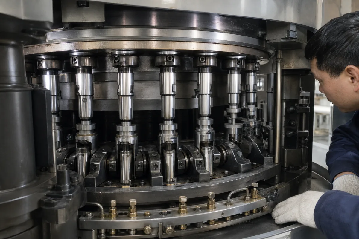
Lower punch assembly in a rotary tablet press turret: fill-depth cams, sealed punch guides and the punch bar under load
The lower punch as it rides in the turret of a rotary tablet press · fill depth set by its cam position (6–20 mm in one IMA example, adjustable in 0.01 mm steps), a 0–10 mm metering lift, the sealing problem of a keyed punch in an oiled guide, and the impact of a free-falling upper punch
A lower punch does more than form the underside of the tablet. Its height in the die at the end of filling sets the dose, a metering cam trims that height, it is driven down and up by cam tracks every revolution, and its barrel slides in an oiled guide bore a few millimetres below the powder. This page follows the lower punch through the turret rather than the shape of its tip.
Lower punches of rotary tablet presses considered as a moving assembly in the turret: the punch shaft or bar, head and key, its guide bore or sleeve and seals in the lower punch guiding, and the filling, metering and ejection cams that set its height. Tip geometry, tip materials and coatings, multi-tip punches and tooling standards are covered on the Pharmaceutical tablet press punch tip page; dies, complete presses and tablet coating machines are outside this page.
CNFX editorial research · Sources checked October 13, 2026 · 4 sources
Dose volume set by where the lower punch sits: interchangeable filling cams, 6–20 mm depth in 0.01 mm steps and a 0–10 mm metering lift
IMA's patent describes the conventional arrangement: a fixed filling cam pulls the lower punches down to form a dosing chamber of set volume, and the cam is swapped for another to change the lower punch position, so volume changes only in discrete steps; an adjustment cam downstream makes finer or intermediate corrections. Its own design moves two filling cams with rotary electric motors, giving, in its example, depths from a maximum of 20 mm to a minimum of 6 mm, a 14 mm range, in intervals of about 0.01 mm. [1]
Korsch's patent describes the lower punches being raised by 0 to 10 mm from their lowest filling position by the metering unit to give a net fill, and states that filling depths of 10 to 25 mm are needed for acceptable two-layer tablets. Fette's rotor patent notes that outside the pressing stations the punches are guided by cams, the lower punches including the cams that eject the tablets. [2][3]
Ask for the filling depth range the lower cam set covers, how the metering cam is adjusted and read, and which cams must be changed for a different tablet weight or a bilayer product.
02
Keeping barrel lubricant out of the powder: why a keyed lower punch is hard to seal, and out-of-round shafts in ceramic sleeves
Fette's patent sets out the problem. Punch shafts run in bores of the punch guiding; a parallel key in a groove stops them rotating, and seals keep pressing material out of the bore and lubricant in. A seal cannot work across the key groove, so the shaft must not pass through a seal in that region. [3]
Its answer is a shaft with an out-of-round cross-section, such as a rounded rectangle, triangle or polygon, in a guide sleeve with a matching bore, which removes the key and screws. With ceramic guide sleeves the patent says lubrication of the punch shaft is no longer needed, and so-called black spots and punch blocking do not occur; sealing rings with a matching inner profile at the ends of the bore also act as strip-off members. [3]
William Cecil's earlier rotary press patent takes another route: the die table is compartmentalised from the oiled punch guides, and oil circulated in the lower compartment lubricates the lower punch turret bores up to a seal, so powder dust stays in the die table compartment. [4]
Ask whether the lower punch guides are oil-lubricated, sealed, or unlubricated sleeves; what seal sits at the top of each lower bore; and how the seal is changed.
03
The punch bar: a 5.25 in bar with a screw-in tip, and the blow of an upper punch falling up to 10 mm onto it
In Cecil's design the lower punch is a punch bar about 5.25 in long with a barrel of about 0.875 to 0.998 in diameter, holding a tip insert in an internally threaded opening of about 0.625 in, so the tip can be changed for another tablet thickness or shape without pulling the bar from the turret; a split spacer is clamped around the lower punch tip during die changes. [4] Editorial calculation: 5.25 in ≈ 133.4 mm; 0.875–0.998 in ≈ 22.2–25.3 mm; 0.625 in ≈ 15.9 mm.
Korsch's patent records a load the lower punch face has to take: with a rigid catch rail low on the cam carrier, upper punches can still plunge up to 10 mm into the die below the upper pressure roller, and if they fall freely at speed they strike the pressing faces of the lower punches with great force, damaging the punches. Its adjustable initial-pressure rail limits that, for example to at most 3.3 mm instead of 6 to 8 mm in its example. [2]
Ask for the bar length and barrel tolerance, whether the tip is integral or screw-in, and how the press prevents upper punches dropping onto the lower punch faces when running without powder.
04
What to send for tablet press lower punches and their guides
Paste it into your enquiry below or into an email to a maker, then replace every bracket.
Press: [make and model; turret stations; tooling standard]
Punch: [bar length; barrel diameter; head form; key; integral or screw-in tip]
Fill: [tablet weight; filling depth range; metering cam; bilayer]
Guides: [oiled bores, sealed bores or unlubricated sleeves; seal type]
Product: [black-spot or contamination limits; cleaning and changeover]
Explore company information and manufacturing capabilities, then discuss the scope of your project with a relevant supplier.
Share this page
Compiled and source-reviewed by the CNFX editorial team.
Each manufacturer above links to the page on that company's own website where the product is listed, with the date we checked it. How we source and review
· Page last updated 13 October 2026
Buyer questions
How does the lower punch set tablet weight?
The filling cam fixes how far the lower punch drops in the die, which sets the dosing volume; a metering cam then raises it, by 0 to 10 mm in Korsch's description, to trim the fill. [1][2]
Can fill depth be changed without swapping cams?
IMA patented motor-driven filling cams that cover 20 mm to 6 mm depth in about 0.01 mm steps in its example, instead of changing cams. [1]
Why do lower punch guides cause black spots?
Barrel lubricant can reach the powder; Fette notes a keyed shaft cannot be sealed across its key groove, and proposes out-of-round shafts in ceramic sleeves that need no lubrication. [3]
Can lower punch tips be changed without removing the punch?
In Cecil's patented press, the lower punch bar takes a threaded tip insert that can be replaced without removing the bar from the turret. [4]
Sources and what still needs a direct check
Sources checked 2026-10-13. Filling cam design and depths come from an IMA patent; metering lift, bilayer filling depths and punch impact from a Korsch patent; punch guide sealing from a Fette patent; punch bar dimensions and compartmented lubrication from William Cecil's patent.