Editorial Technical Reference

Rotary Feeder / Screw Feeder

This page explains how Rotary Feeder / Screw Feeder is classified within Machinery and Equipment Manufacturing. Technical values and manufacturer relationships are research references; confirm the current specification and supplier evidence for each order.

Technical Definition & Core Assembly

A mechanical device that precisely meters and transfers dry bulk materials or powders from a hopper into a process stream.
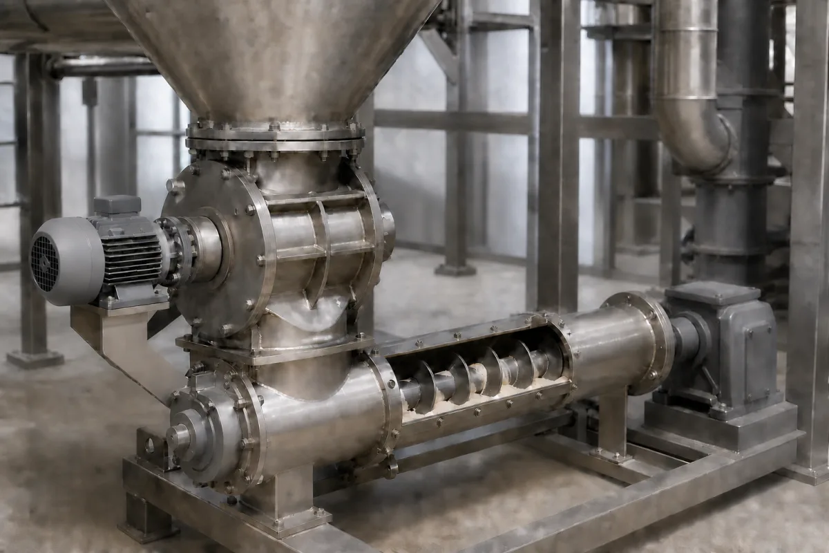
Representative product image. Confirm appearance and specifications with the manufacturer.

Product Specifications

Technical details and manufacturing context for Rotary Feeder / Screw Feeder

Definition
The Rotary Feeder / Screw Feeder is a component used in machinery and equipment manufacturing, specifically within an Agent Injection System. It is responsible for the controlled, volumetric feeding of solid agents such as catalysts, additives, or powders from a storage hopper into the main process line. This feeder ensures consistent flow rates, prevents backflow of process gases, and maintains system pressure isolation. The device operates on the principle of volumetric displacement: material from an overhead hopper fills the pockets of a rotating rotor (in a rotary feeder) or the flights of a rotating screw (in a screw feeder). As the rotor or screw turns at a controlled speed, a measured volume of material is discharged from the outlet. In rotary feeders, the tight clearance between the rotor and housing provides an airlock function, preventing gas exchange between the inlet and outlet sides. The feeder is available in materials such as cast iron, stainless steel, and carbon steel. Key parameters include throughput (0.5–50 m³/h), rotor speed (10–60 rpm), metering accuracy (±1–3%), operating pressure (1.0–1.6 MPa), operating temperature (-20–150 °C), shaft seal type (PTFE, with options for packing, lip seal, or mechanical seal), housing material (SS304, also SS316 or carbon steel, per ASTM A240), rotor material (SS316, per ASTM A240), motor power (0.75–11 kW, per IEC 60034), voltage (380–480 V AC, 50/60 Hz, 3-phase, per IEC 60038), ingress protection (IP54–IP65, per IEC 60529), noise level (≤75 dB(A) at 1 m, per ISO 3746), and weight (50–500 kg). These values are reference ranges and must be verified for the specific model and application. Standards listed are for procurement and verification reference only, not proof of certification or compliance. Always confirm model-specific values and standards with the legal manufacturer or supplier.
Working Principle
Material from an overhead hopper fills the pockets of a rotating rotor (rotary feeder) or the flights of a rotating screw (screw feeder). As the rotor or screw turns at a controlled speed, a measured volume of material is discharged from the outlet. The tight clearance between the rotor and housing (in rotary feeders) provides an airlock function, preventing gas exchange between the inlet and outlet sides of the system.
Common Materials
Cast Iron, Stainless Steel, Carbon Steel
Technical Parameters
ParameterTypical rangeNotes & selection driver
Throughput0.5–50 m³/hDepends on rotor size and speed
Rotor Speed10–60 rpmAdjustable for metering accuracy
Metering Accuracy±1–3 %Depends on material flowability
Operating Pressure1.0–1.6 MPa
Operating Temperature-20–150 °CHigher temps require special seals
Shaft Seal TypePTFEOptions: packing, lip seal, mechanical seal
Housing MaterialSS304Also available: SS316, carbon steelASTM A240
Rotor MaterialSS316Wear-resistant coating optionalASTM A240
Motor Power0.75–11 kWDepends on rotor size and material densityIEC 60034
Voltage380–480 V AC50/60 Hz, 3-phaseIEC 60038
Ingress ProtectionIP54–IP65Higher IP for dusty environmentsIEC 60529
Noise Level≤75 dB(A)At 1 m distanceISO 3746
Weight50–500 kgDepends on size and material

Ranges are indicative industry figures for RFQ preparation, not a supplier commitment. Confirm every value and standard with the legal manufacturer before ordering.

Components / BOM
  • Rotor / Screw Part
    The rotating element with pockets or flights that captures and conveys the material.
    Material: Stainless Steel, Cast Iron, or Abrasion-Resistant Alloy
  • Housing / Casing Part
    Encloses the rotor/screw, provides inlet and outlet ports, and supports bearings.
    Material: Cast Iron or Carbon Steel
  • Drive Assembly
    Typically an electric motor and gear reducer that provides controlled rotational power to the rotor/screw.
    Material: Various (Motor: Copper, Steel; Gearbox: Steel)
  • Shaft Seals Part
    Prevent material leakage and ingress of contaminants along the drive shaft.
    Material: PTFE, Rubber, Mechanical Seal Materials
  • Bearings
    Support the rotor/screw shaft and allow smooth rotation.
    Material: Chrome Steel (Ball/Roller Bearings)

Applied To / Applications

This component is essential for the following industrial systems and equipment:

Industrial Ecosystem & Supply Chain Structure

Complementary Systems
Downstream Applications
Specialized Tooling

Application Fit & Sizing Matrix

Operational Limits
pressure: Up to 1 bar differential pressure, vacuum to 0.5 bar positive pressure
flow rate: 0.1 to 300 m³/h depending on screw diameter and speed
temperature: -20°C to 200°C (standard), up to 400°C with special seals/heating
material size: Up to 10 mm particle size (standard), larger with special designs
moisture content: Up to 15% moisture (standard), higher with special coatings
Media Compatibility
✓ Plastic pellets (polyethylene, polypropylene) ✓ Food-grade powders (flour, sugar, cocoa) ✓ Mineral powders (cement, limestone, fly ash)
Unsuitable: Highly abrasive materials (silica sand, metal powders) without hardened components
Sizing Data Required
  • Bulk density of material (kg/m³)
  • Required throughput capacity (kg/h or m³/h)
  • Material flow characteristics (angle of repose, cohesion, abrasiveness)

Reliability & Engineering Risk Analysis

Failure Mode & Root Cause
Bearing failure
Cause: Contamination from process material ingress or inadequate lubrication due to dust accumulation and seal degradation
Screw flight wear/breakage
Cause: Abrasive material handling causing gradual erosion or impact damage from tramp metal or oversized particles
Maintenance Indicators
  • Excessive vibration or unusual grinding/rattling noise during operation
  • Visible material leakage around shaft seals or housing joints indicating seal failure
Engineering Tips
  • Implement regular lubrication schedule with appropriate grease type and install effective shaft seals/air purge systems to prevent material ingress into bearings
  • Install magnetic or screening protection at inlet to remove tramp metal and monitor screw wear through periodic thickness measurements or vibration analysis

Indicative industry ranges for design and RFQ preparation. Confirm the exact figures and applicable standard with the manufacturer before specifying.

Compliance & Manufacturing Standards

Applicable Standards
ANSI/CEMA 350-2015 - Screw Conveyors for Bulk Materials DIN 15262-1:2012 - Continuous mechanical handling equipment - Screw conveyors

Quoted from the published standard.

Manufacturing Precision
  • Shaft concentricity: +/-0.05mm
  • Housing flatness: 0.2mm per meter
Quality Inspection
  • Dimensional verification with CMM (Coordinate Measuring Machine)
  • Pressure decay leak test for sealing integrity

Manufacturers of Rotary Feeder / Screw Feeder

Manufacturer profiles associated with Rotary Feeder / Screw Feeder.

Sourcing Rotary Feeder / Screw Feeder from China?
Tell us your specification and target quantity — we will match it against manufacturer records and come back with the factories that fit.
Request manufacturers We manufacture this

Manufacturer listings support early research and capability understanding. They are not certification, ranking, or transaction guarantees.

Technical documentation
Request current drawings, revision history, and a signed specification sheet.
Manufacturing capability
Verify equipment lists, process limits, capacity, and representative production evidence.
Inspection readiness
Confirm test methods, calibrated equipment, sampling plans, and traceable reports.
Supplier transparency
Check the legal entity, factory address, ownership, certifications, and direct contacts.

CNFX does not score or rank suppliers. Buyers must verify all claims and documents with the legal manufacturer before ordering.

Supply Chain Compatible Machinery & Devices

Automated Powder Coating System

Integrated industrial system for applying dry powder coatings to metal substrates.

Explore Specs →
Centrifugal Pump Impeller

The centrifugal pump impeller is a critical rotating component that converts mechanical energy from the motor into kinetic energy in fluid systems.

Explore Specs →
High-Precision CNC Laser Cutting Machine

Computer-controlled industrial machine using focused laser beams to cut sheet metal with micron-level accuracy.

Explore Specs →
Industrial-Grade Hydraulic Cylinder Piston Rod

This industrial-grade piston rod is a precision-ground cylindrical component designed for use in hydraulic cylinders.

Explore Specs →

Frequently Asked Questions

What is the difference between a rotary feeder and a screw feeder?

A rotary feeder uses a rotating rotor with pockets to displace material, while a screw feeder uses a rotating screw with flights. Both provide volumetric metering, but the rotary feeder also acts as an airlock due to tight clearances, preventing gas exchange. The screw feeder is often used for more continuous flow and may handle different material characteristics.

What materials can be fed with this device?

The device is designed for dry bulk materials or powders, such as catalysts, additives, or other solid agents. The specific material compatibility depends on factors like flowability, abrasiveness, and temperature, and should be verified with the manufacturer.

What are the typical operating conditions?

Reference parameters include operating pressure of 1.0–1.6 MPa, temperature range of -20 to 150 °C, and rotor speed of 10–60 rpm. These are general ranges; actual limits depend on the model and application, so confirm with the supplier.

How do I verify the feeder's specifications for my application?

Always check the model-specific datasheet and confirm values such as throughput, accuracy, materials, and standards with the legal manufacturer or supplier. The listed standards (e.g., ASTM A240) are references for procurement and verification, not guarantees of compliance.

Data Basis

Editorial classification, named public sources where available, and source-reviewed manufacturer records.

Preliminary Technical Classification
This page supports structured research, RFQ preparation, and supplier evaluation. It does not replace buyer-led supplier qualification, standards review, or technical approval.
Buyer enquiry

Request manufacturing insight for Rotary Feeder / Screw Feeder

Ask for use case, specification boundaries, supplier type, and RFQ preparation information for this product.

Where it goes
Straight to the CNFX editorial desk, and to the manufacturer if this product is linked to a claimed profile. Nothing is broadcast to a supplier list.
Your details stay here
We do not sell or rent enquiry data, and we do not add you to a mailing list. Used only to answer this request.
No commission, no middleman
CNFX is a directory. We take no cut of any order and never negotiate on a supplier's behalf.
What we don't claim
A listing is not an endorsement. Qualify every supplier and verify every figure yourself before ordering.

Your business information is used only to process this request.

Thank you! Your message has been sent. We'll respond within 1–3 business days.
Sorry, we couldn't send your message. Please try again, or email us at contact@cnfx.com.

Need to Manufacture Rotary Feeder / Screw Feeder?

Compare manufacturer profiles with relevant product and process capability.

Previous Product
Z-axis Ram/Spindle
Last Product
Get QuotesChat