Editorial Technical Reference

Time Setting Interface

This page explains how Time Setting Interface is classified within Machinery and Equipment Manufacturing. Technical values and manufacturer relationships are research references; confirm the current specification and supplier evidence for each order.

Technical Definition & Core Assembly

User interface component for configuring and adjusting time parameters on a treatment timer device.
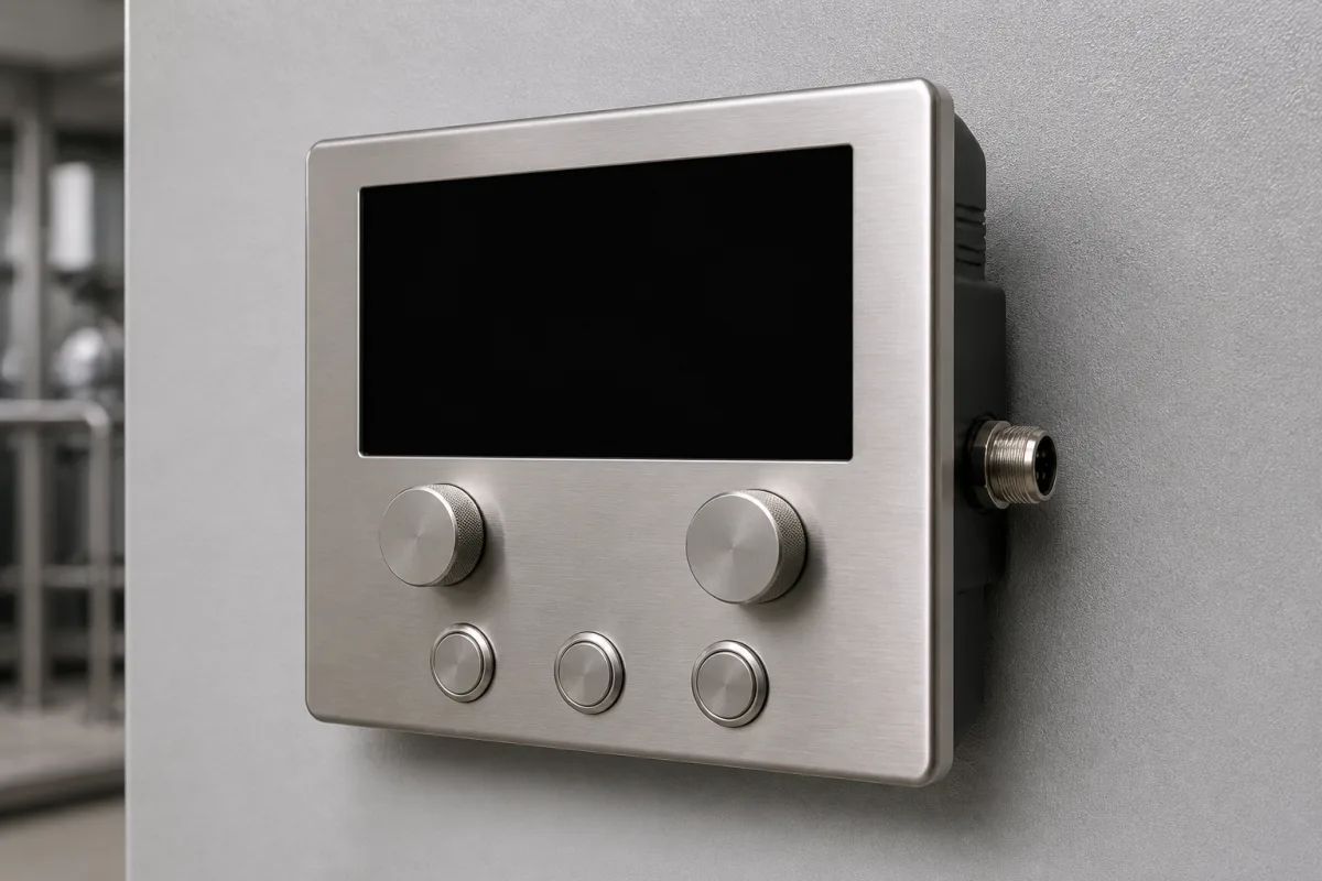
Time Setting Interface in a manufacturing environment
Representative product image. Confirm appearance and specifications with the manufacturer.

Product Specifications

Technical details and manufacturing context for Time Setting Interface

Definition
The Time Setting Interface is a dedicated control panel or digital interface within a Treatment Timer system that allows operators to set, modify, and confirm treatment duration parameters. It serves as the primary human-machine interaction point for programming the operational cycle of the timer, ensuring precise control over treatment processes. The interface is designed for industrial environments, featuring a robust housing made of flame-retardant ABS (UL 94 HB) and a front panel that meets IP54 ingress protection (IEC 60529) for dust and splash resistance. The display is a 4-digit, 7-segment LED, providing clear visibility of the set time. Input is typically via buttons or dials, and the interface converts user input into digital signals transmitted to the timer's central processing unit. The setting range covers 0 to 9999 seconds, with a resolution of 1 second and an accuracy of ±0.1% relative to the set value. The device operates on a 24 V DC supply (24 ±10%) with reverse polarity protection, consuming no more than 5 W at nominal voltage. It is designed for a wide range of environmental conditions: operating temperature from -10 to 50 °C, storage from -20 to 70 °C, and non-condensing humidity from 20% to 80% RH. The dimensions are 96×48×80 mm (W×H×D) with a panel cutout of 92×45 mm, conforming to DIN 43700. The weight varies between 0.3 and 0.5 kg depending on configuration. Materials used include polycarbonate and stainless steel for certain components. This interface is a component intended for integration into a larger treatment timer system; it is not a standalone device. For specific applications, verify model-specific values and standards with the legal manufacturer or supplier.
Working Principle
The Time Setting Interface receives user input via buttons, touchscreen, or dials to define a time value. This input is converted into a digital signal or command, which is then transmitted to the timer's central processing unit to program the countdown or delay function for the treatment cycle. The interface ensures precise control by allowing adjustments in 1-second increments within a range of 0 to 9999 seconds. The accuracy of the set time is maintained within ±0.1% of the set value. The interface also provides visual feedback through a 4-digit LED display, confirming the entered time. The device is powered by a 24 V DC supply with reverse polarity protection, and its power consumption is limited to 5 W. The interface is designed to operate reliably in industrial environments, with an IP54-rated front panel and a flame-retardant ABS housing. It is important to note that the interface is a component and must be integrated with a compatible timer system. For detailed integration and operation, refer to the manufacturer's documentation.
Common Materials
Polycarbonate, Stainless Steel
Technical Parameters
ParameterTypical rangeNotes & selection driver
Setting Range0–9999 sCovers typical treatment durations
Resolution1 sMinimum increment for time setting
Accuracy±0.1 %Relative to set value
Display TypeLED7-segment, 4-digit
Input Voltage24 ±10% V DCReverse polarity protected
Power Consumption≤5 WAt nominal voltage
Operating Temperature-10–50 °CNon-condensing
Storage Temperature-20–70 °CFor long-term storage
Humidity Range20–80 % RHNon-condensing
Ingress ProtectionIP54Dust and splash proofIEC 60529
Housing MaterialABSFlame retardantUL 94 HB
Weight0.3–0.5 kgDepending on configuration
Dimensions (W×H×D)96×48×80 mmPanel cutout 92×45 mmDIN 43700

Ranges are indicative industry figures for RFQ preparation, not a supplier commitment. Confirm every value and standard with the legal manufacturer before ordering.

Components / BOM
  • Control Buttons / Keypad Part
    Provides tactile input for incrementing, decrementing, and confirming time values.
    Material: Silicone Rubber or ABS Plastic
  • Display Module
    Visually presents the current time setting and system status to the user.
    Material: Glass or Polycarbonate with LCD/LED layer
  • Interface Circuit Board
    Processes user input signals and communicates with the main timer controller.
    Material: FR-4 PCB with electronic components

Application & selection

Application Fit & Sizing Matrix

Operational Limits
pressure: 0 to 1 bar (non-pressurized environment)
other spec: IP65 ingress protection rating, 24V DC power supply
temperature: -20°C to +70°C
Media Compatibility
✓ Clean room environments ✓ Laboratory settings ✓ Medical device assemblies
Unsuitable: High-vibration industrial machinery with particulate contamination
Sizing Data Required
  • Timer resolution requirement (seconds/minutes/hours)
  • Number of programmable time parameters
  • Required interface type (touchscreen/buttons/digital display)

Risk, maintenance & compliance

Reliability & Engineering Risk Analysis

Failure Mode & Root Cause
Interface Button Wear
Cause: Repeated mechanical actuation leading to contact degradation or membrane fatigue
Display Malfunction
Cause: Environmental exposure (moisture, dust) or electrical surge damaging LCD/OLED components
Maintenance Indicators
  • Unresponsive or erratic button response during time adjustments
  • Flickering, dimming, or partial display failure of the time readout
Engineering Tips
  • Implement regular cleaning with appropriate solvents to prevent contaminant buildup in button mechanisms and display seals
  • Install surge protection and environmental enclosures to shield against electrical transients and harsh conditions

Indicative industry ranges for design and RFQ preparation. Confirm the exact figures and applicable standard with the manufacturer before specifying.

Compliance & Manufacturing Standards

Applicable Standards
ANSI/ASQ Z1.4-2008 - Sampling Procedures and Tables for Inspection by Attributes CE Marking - Directive 2001/95/EC on General Product Safety

Quoted from the published standard.

Manufacturing Precision
  • Time Display Alignment: +/-0.5°
  • Button Actuation Force: 2.5N +/-0.3N
Quality Inspection
  • Functional Durability Test (10,000 cycles)
  • Environmental Sealing Test (IP65 rating verification)
Technical documentation
Request current drawings, revision history, and a signed specification sheet.
Manufacturing capability
Verify equipment lists, process limits, capacity, and representative production evidence.
Inspection readiness
Confirm test methods, calibrated equipment, sampling plans, and traceable reports.
Supplier transparency
Check the legal entity, factory address, ownership, certifications, and direct contacts.

Compare the published product scope and source details, then include your specifications and quantity in an enquiry.

Manufacturers of Time Setting Interface

Manufacturer profiles associated with Time Setting Interface.

Sourcing Time Setting Interface from China?
Tell us your specification and target quantity — we will match it against manufacturer records and come back with the factories that fit.
Request manufacturers We manufacture this

Explore company information and manufacturing capabilities, then discuss the scope of your project with a relevant supplier.

Buyer enquiry

Request manufacturing insight for Time Setting Interface

Ask for use case, specification boundaries, supplier type, and RFQ preparation information for this product.

Where it goes
Straight to the CNFX editorial desk, and to the manufacturer if this product is linked to a claimed profile. Nothing is broadcast to a supplier list.
Your details stay here
We do not sell or rent enquiry data, and we do not add you to a mailing list. Used only to answer this request.
No commission, no middleman
CNFX is a directory. We take no cut of any order and never negotiate on a supplier's behalf.
What to include
Share your product specifications, quantity, destination and target delivery date.

Your business information is used only to process this request.

Thank you! Your message has been sent. We'll respond within 1–3 business days.
Sorry, we couldn't send your message. Please try again, or email us at [email protected].

Frequently Asked Questions

What is the setting range of the Time Setting Interface?

The setting range is 0 to 9999 seconds, covering typical treatment durations. The resolution is 1 second, allowing precise adjustments.

What is the accuracy of the time setting?

The accuracy is ±0.1% relative to the set value. This ensures precise control over treatment durations.

What are the power requirements?

The interface operates on a 24 V DC supply with a tolerance of ±10%. It has reverse polarity protection and consumes no more than 5 W at nominal voltage.

What environmental conditions can it withstand?

It operates in temperatures from -10 to 50 °C, can be stored from -20 to 70 °C, and works in non-condensing humidity from 20% to 80% RH. The front panel is IP54 rated for dust and splash resistance.

Related equipment

Applied To / Applications

This component is essential for the following industrial systems and equipment:

Data Basis

Editorial classification, named public sources where available, and source-reviewed manufacturer records.

Preliminary Technical Classification
This page supports structured research, RFQ preparation, and supplier evaluation. It does not replace buyer-led supplier qualification, standards review, or technical approval.

Need to Manufacture Time Setting Interface?

Compare manufacturer profiles with relevant product and process capability.

Previous Product
Z-axis Ram/Spindle
Last Product
Get QuotesChat