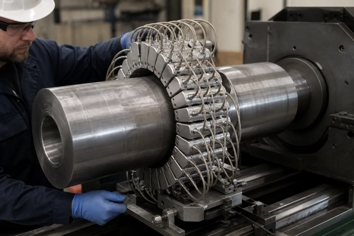
Ultrasonic transducer array for encircling bar and tube inspection
Encircling ultrasonic transducer arrays for automated bar and tube testing · rings of single-element probes versus annular and multi-probe phased arrays, element and channel counts, diameter ranges and line speed
An encircling ultrasonic transducer array surrounds a bar or tube as it passes through a testing machine, so that its cross-section is inspected for internal and surface flaws as it moves along the line; in the Karl Deutsch ring system neither the bar nor the probes rotate. It is built either as a ring of single-element probes in a water-filled chamber or as phased-array probes whose elements are fired electronically to form straight and angled beams. Ask three things first: whether the array is a probe ring or a phased array, how many elements and parallel channels cover your diameter range, and what flaw size and line speed it is proven for.
Ultrasonic transducer arrays that encircle bars, billets and tubes for automated in-line flaw testing: rings of angle-beam and straight-beam probes in immersion chambers, annular ring phased arrays, and sets of curved phased-array probes spaced around the circumference, with their coupling and channel electronics. Ultrasonic washers for vegetables and fruit are covered on the Industrial ultrasonic vegetable washer page. Ultrasonic cleaning transducers, medical imaging probes and hand-held flaw detector probes are outside this page.
CNFX editorial research · Sources checked October 12, 2026 · 4 sources
Choose a ring of single-element probes or an annular phased array
Karl Deutsch's ECHOGRAPH-HRPS tests bars by immersion: the bar passes through a water chamber with probe cassettes mounted around its circumference and no mechanical rotation. For bars the company reports a setup of 16 angle-beam probes, which detect surface defects, and 5 straight-beam probes, which detect core defects, as proven for 100% cross-sectional coverage; each line-focused angle probe covers 30° of the bar surface independently of the bar diameter. [1]
The same leaflet describes the phased-array alternative: the bar is entirely enclosed by an annular ring array that can form straight or angled beams. Karl Deutsch lists fast change-over to other diameters and electronic adjustment of all test parameters as advantages, and, as the drawback, the electronic testing channels and extensive probe arrays the technique requires. [1]
The leaflet's text gives a bar diameter range of 7 mm to 93 mm while its specimen table lists 10 mm to 90 mm, with ovality up to 1% of D and straightness deviation up to 1 mm/m; ask the supplier which range applies to the configuration offered. [1]
Editorial calculation: 16 angle-beam probes × 30° each = 480° of surface tracks, a third more than one 360° circumference. [1]
Give the supplier the material, bar or tube diameter range and wall thickness, ovality and straightness, surface condition (black, bright, machined), bar length, line speed, the reference flaw sizes and depths to be detected (flat-bottom holes, notches), the flaw orientations of concern, coupling method acceptable, and the documentation required.
02
Count elements and parallel channels for the diameter range and line speed
Karl Deutsch's ECHOGRAPH STPS PAUT replaces the probe ring with five phased-array probes spaced 72° apart around the bar, each producing a sector scan of up to 20 shots, with up to 120 parallel test channels active and overlapping sound fields for 100% coverage of the cross-section. Coupling is by guided water jets (squirters), and the system tests at up to 2 m/s. [2]
Its leaflet lists round bars of 16–130 mm as standard (8–150 mm as an option), ovality up to 2% of D, straightness deviation up to 2 mm/m, bar temperature up to 60 °C and sensitivity of 0.7–2 mm flat-bottom hole depending on diameter, surface, material and straightness. [2]
In a Karl Deutsch conference paper on bar and tube systems, an immersion tank supports array setups of up to 512 elements for full cross-section coverage, and a pipe-weld system drives three curved phased arrays from electronics with 320 parallel channels; the authors chose curved arrays to reduce the steering angles needed and to raise sensitivity, and they use CIVA simulation to specify the number and size of elements, the curvature and the test frequency. [3]
Innerspec lists pass-through phased-array systems for bars and tubes with up to 128 elements for non-rotating bars of 10–260 mm at up to 2 m/s, and up to 256 elements for rotating tubes and bars of 10–65 mm (up to 50 m/min) and 35–503 mm (up to 60 m/min), all with full parallel firing of the elements. [4]
Editorial calculation: at 2 m/s a 6 m bar (an assumed length) passes the array in 6 ÷ 2 = 3 seconds, so all shots for every cross-section must be fired and evaluated within that time. [2]
03
Compare encircling array layouts by coverage, channels and diameter
Each row is one layout as its maker describes it.
Layout
How it covers the bar or tube
Published figures
Ring of single-element probes in immersion
Angle probes for surface flaws, straight probes for core
16 angle + 5 straight probes; 30° per angle probe; bars 7–93 mm in text, 10–90 mm in table. [1]
Explore company information and manufacturing capabilities, then discuss the scope of your project with a relevant supplier.
Share this page
Compiled and source-reviewed by the CNFX editorial team.
Each manufacturer above links to the page on that company's own website where the product is listed, with the date we checked it. How we source and review
· Page last updated 13 October 2026
Buyer questions
How many probes does a ring array for bars use?
Karl Deutsch reports 16 angle-beam and 5 straight-beam probes for full cross-section coverage of bars, each angle probe covering 30° of the surface. [1]
What is the trade-off of an annular phased array?
Karl Deutsch lists fast change-over and electronic adjustment against the electronic testing channels and extensive probe arrays it requires. [1]
How fast can encircling arrays test bars?
Karl Deutsch's STPS PAUT and Innerspec's non-rotating bar system both list speeds up to 2 m/s. [2][4]
Sources and what still needs a direct check
Sources checked 2026-10-12. Karl Deutsch and Innerspec describe their own ultrasonic bar and tube testing systems; the conference paper is by Karl Deutsch engineers.