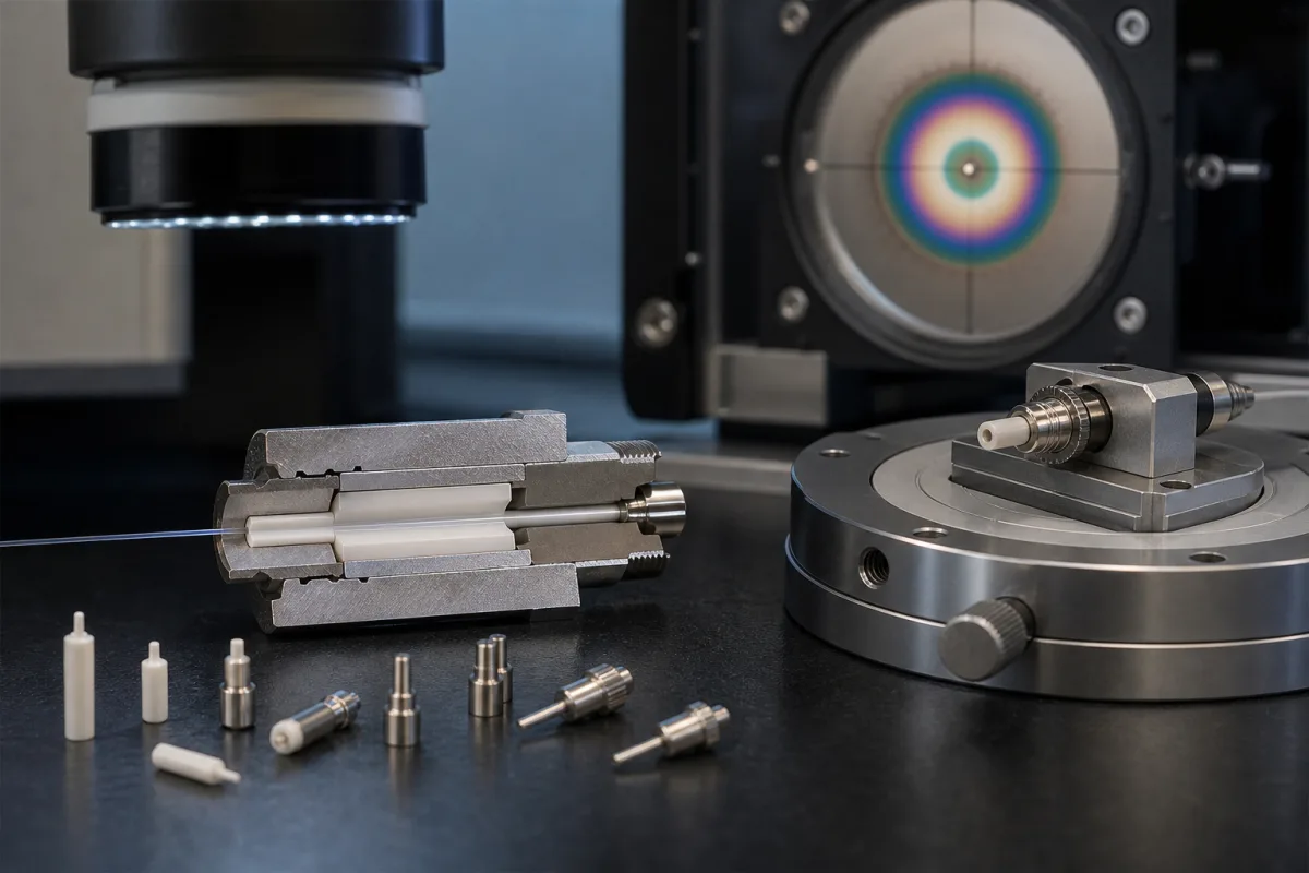
Fibre optic connector ferrules · 2.5 mm and 1.25 mm zirconia ferrules, bore and concentricity tolerances, PC and APC end-face geometry under GR-326 and IEC 61755-3-1, multi-fibre MT ferrules
A fibre optic ferrule is the precision cylinder (or, for array connectors, the rectangular block) that holds the stripped fibre at the centre of a connector so two fibres meet end to end in a mating adapter. Fix three things before ordering: the connector family and ferrule diameter, the material and end-face geometry, and the bore diameter, concentricity and other tolerances that set the connection loss.
Ferrules for single-fibre and multi-fibre optical connectors — ceramic, metal and polymer — supplied as blanks or finished parts for connector and assembly makers. Complete connectors, mating adapters and sleeves, patch cords and fusion splice protectors are outside this page.
CNFX editorial research · Sources checked October 12, 2026 · 5 sources
The Fiber Optic Association's connector reference describes fibre optic connectors as plugs with a protruding ferrule that holds and aligns the fibre, mated through an adapter. ST, SC, FC, FDDI and ESCON connectors share a 2.5 mm (about 0.1 in) ferrule, so they can be cross-mated with hybrid adapters; LC uses a 1.25 mm ferrule, half the size of SC, shared with MU and LX-5, and newer duplex connectors such as CS and SN also use 1.25 mm ferrules. [1]
For array connectors, the FOA describes the MPO as using a plastic ferrule holding 12 or 16 fibres in a row, with alignment by pins in one ferrule and holes in the other, and the MT-RJ as a duplex connector with both fibres in a single polymer ferrule. It lists the TIA-604 FOCIS intermateability standards for each family — for example FOCIS-2 for ST, FOCIS-3 for SC, FOCIS-4 for FC and FOCIS-10 for LC. [1]
Editorial note: name the FOCIS (or IEC) interface the ferrule must meet as well as the diameter. [1]
Give the supplier the connector family and interface standard, ferrule diameter and length, material, bore diameter and tolerance, concentricity, end-face geometry (PC, UPC, APC angle), chamfer or entry cone, flange or holder if pre-assembled, multimode or singlemode, fibre count for MT types, inspection reports and quantity.
02
Set material, end-face geometry and tolerances
The FOA says the ceramic ferrule, which appeared in Japan in the mid-1980s, changed connector design: it was hard and precise, fibres could be located accurately and ferrules could be allowed to touch. Convex ferrules for physical contact (PC) reduced connector losses below 0.3 dB for both multimode and singlemode, compared with earlier non-contact designs that could not get below 0.3 dB because of Fresnel reflection at the air gap. Ferrules are made of ceramic, metal or plastic, and some early FC connectors used ceramic inside stainless steel. [1]
The FOA's history of the Biconic notes that fibres were glued into a 125 µm bore with epoxy, and that for singlemode the ferrules were ground to centre the fibre core to reduce loss. [1]
For single-mode work the ceramic is zirconia. IEC 61755-3-1:2024 defines the dimensional limits of the optical interface for single-mode connectors with 2,5 mm or 1,25 mm diameter cylindrical zirconia (ZrO2) ferrules, non-angled and physically contacting, so that they meet the fibre-to-fibre requirements of IEC 61755-2-1; it states that ferrules of the material it specifies suit all the operating service environments of IEC 61753-1, and points to the IEC 61754 series for ferrule dimensions and features. [2]
The 2024 second edition adds a Variant 2 interface whose fibre core axis is not oriented towards the connector guide key, alongside the original Variant 1, keeps both intermateable within a performance grade and backwards compatible with the 2006 edition, and adds Grade B and Grade C interface requirements and a mean fibre core eccentricity statistic. [2]
Kyocera's standard ferrule list shows the range a single maker catalogues in zirconia: single-mode ferrules for SC/FC (PC, pencil and step types), ST, LC and MU connectors, multimode ferrules for SC/FC, ST and LC, ferrules for attenuators in Φ2.5 and Φ1.25, capillaries, and special inner-diameter ferrules. Flanged versions use a stainless steel flange, and LC flanges are stainless steel or nickel-plated brass. [3]
Editorial note: because loss depends on how well the fibre core is centred, ask for the bore diameter tolerance against your fibre's cladding diameter and for measured concentricity, and ask how the end-face geometry of PC parts is measured. [1]
03
Specify bore, outer diameter and concentricity
Ferrule data sheets state the tolerances that place the fibre core. Seiko Instruments' SNZ-1A 2.5 mm single-mode zirconia ferrule, in a Fiber Optic Center data sheet, lists an outside diameter of 2499.0 µm with a 0.5 µm tolerance, hole diameters of 125 µm (S5) or 126 µm (S6), a hole diameter tolerance of +1.0/-0 µm and hole eccentricity of 0.5 µm or less. The sheet says it uses a conical-tip zirconia ferrule for Angle PC polishing, fits SC and FC housings, and that the properties given "are typical values, and are not intended for use in preparing specifications". [4]
Kyocera codes concentricity into its single-mode inquiry code, with two grades: 0.0010 mm and 0.0014 mm. Its special inner-diameter ferrules run from a Φ0.080 mm bore (+0.001/0 mm, concentricity 0.001 mm) to Φ0.435 mm (+0.010/0 mm, 0.010 mm), with custom design also offered. [3]
Editorial calculation: a 125 µm bore with a +1.0/-0 µm tolerance gives a hole of 125.0 to 126.0 µm, so the choice between the S5 and S6 bore depends on the measured cladding diameter of the fibre to be terminated; Kyocera's two concentricity grades of 0.0010 mm and 0.0014 mm equal 1.0 µm and 1.4 µm.
Editorial note: the FOA's Biconic history shows why this matters — single-mode loss fell once the ferrule was ground to centre the fibre core. Ask for the measured bore, outer diameter and concentricity per lot, not only the nominal grade. [1]
State the connector type, single-mode or multimode, bore code and tolerance, concentricity grade, flange material if flanged, and the end shape (PC, pre-dome, step, pencil or APC blank).
04
Check end-face geometry after polishing
Senko's polishing application note (Rev. 01, November 2023) says the acceptable 3D end-face geometry of ceramic ferrules is defined by GR-326-CORE in North America and measured under IEC 61300-3-47 by interferometry, with the IEC 61755 series covering angle polishing, ferrule geometry and materials. The parameters are radius of curvature, apex offset and fibre height, also called undercut. [5]
Senko's summary table gives, for PC ferrules under GR-326 Core Issue 4, a radius of 7–25 mm, apex offset below 50 μm and protrusion of 50 nm; for PC ferrules under IEC 61755-3-1, 10–25 mm, below 70 μm and 100 nm; and for APC ferrules under both, 5–12 mm, below 70 μm and 100 nm. Allowed undercut for PC is set by a formula in the ferrule radius R, U = -.02R3 + 1.3R2 -31R +325, and is -100 nm for APC. [5]
Senko explains that a smaller radius allows a deeper fibre recess, because the smaller ferrule radius compresses more in physical contact. It reports losses below 0.5 dB per mated pair for epoxy-and-polish connectors, and for its own zirconia connectors a mean insertion loss of 0.12 dB or less and a maximum of 0.25 dB or less for over 97% of randomly mated samples, which it places in IEC 61753-1 Grade B. [5]
Editorial note: these limits apply to the polished connector, so a blank-ferrule order should state which end shape is supplied and who polishes; if the ferrule maker supplies pre-domed parts, ask for interferometer data against the limits above.
05
Bore, concentricity and end-face reports to request with a ferrule quote
Ask any supplier for the interface standard, bore and concentricity data and end-face inspection method for the ferrule quoted. [1]
06
Outer diameter, bore, material, end face, MT pin holes and flange: what each one sets
The bore and end-face rows decide loss: the FOA's physical-contact history and Senko's geometry limits both trace connection loss to how well the fibre core is centred and how the polished faces meet. [1][5]
Stainless steel or nickel-plated brass in one catalogue. [3]
Drawing and material.
07
Bore, outer diameter, concentricity, end-face radius and insertion loss for a ferrule order
Hole diameter, outer diameter and concentricity carry published values from the Seiko sheet and Kyocera's list; length, surface roughness, return loss and weight have none in the reviewed sources and come from the supplier's drawing. [4][3]
Field
What it means and published values
Ask the supplier for
Hole Diameter
125 or 126 µm, +1.0/-0 µm in one sheet; special bores Φ0.080–0.435 mm. [4][3]
Diameter; tolerance.
Outer Diameter
2.5 mm or 1.25 mm; 2499.0 µm with 0.5 µm tolerance in one sheet. [1][4]
Tolerance.
Length
Per connector design.
Length.
Concentricity
0.0010 or 0.0014 mm grades; hole eccentricity 0.5 µm or less in one sheet. [3][4]
Measured value.
Surface Roughness
End-face and outer finish.
Ra.
Operating Temperature
IEC 61755-3-1 zirconia suits all IEC 61753-1 service environments. [2]
Explore company information and manufacturing capabilities, then discuss the scope of your project with a relevant supplier.
Share this page
Compiled and source-reviewed by the CNFX editorial team.
Each manufacturer above links to the page on that company's own website where the product is listed, with the date we checked it. How we source and review
· Page last updated 13 October 2026
Buyer questions
What size is an SC or ST ferrule?
The FOA says ST, SC and FC share a 2.5 mm ferrule. [1]
What size is an LC ferrule?
1.25 mm, half the size of SC; MU and LX-5 use the same ferrule. [1]
What are fibre optic ferrules made of?
The FOA lists ceramic, metal and plastic ferrules, with plastic for MPO; IEC 61755-3-1 covers zirconia ferrules for single-mode connectors. [1][2]
Senko's summary gives 7–25 mm under GR-326 and 10–25 mm under IEC 61755-3-1 for PC, and 5–12 mm for APC. [5]
Sources and what still needs a direct check
Sources checked 2026-10-12. The Fiber Optic Association publishes a connector identification and history reference. IEC 61755-3-1 is cited from its published abstract only; GR-326 values come from Senko's summary, not from the GR-326 text. Kyocera's list and the Seiko Instruments sheet describe their own ferrules and are not specifications for other makers' parts.