Motor cores · Electrical steel grade and core loss, thickness and lamination factor, stacking method and tolerances
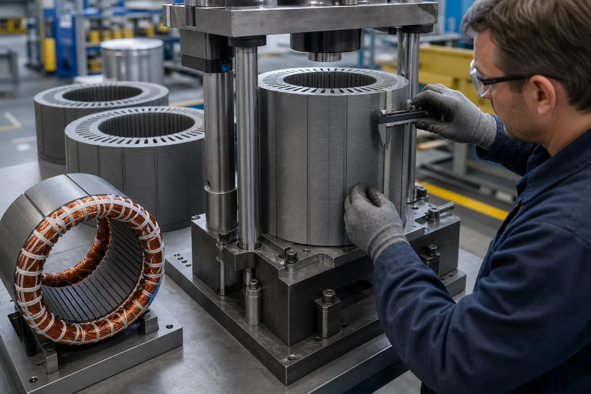
A stator lamination stack is the core of an electric motor stator, built from thin insulated electrical steel laminations punched or cut to shape and joined into a stack. Ask three things first: the steel grade and thickness that set core loss, the stacking method and its effect on the finished core, and the dimensional tolerances for the stack and slots.
Stator (and matching rotor) lamination stacks of non-oriented electrical steel for motors and generators, stamped or laser-cut, interlocked, welded, riveted, glued or self-bonded. Grain-oriented transformer cores, wound stators and complete motors are outside this page.
CNFX editorial research · Sources checked October 11, 2026 · 5 sources
Choose the electrical steel grade, thickness and lamination factor
Nippon Steel's non-oriented electrical steel table cross-references its grades to IEC 60404-8-4 and Chinese GB/T 2521: for example 35H270, M270-35A and 35W270 all mean a maximum core loss W15/50 of 2.70 W/kg (at 1.5 T, 50 Hz) in 0.35 mm steel. Its 0.35 mm grades range from 2.10 to 4.40 W/kg with a lamination factor of at least 95.0%, and its 0.50 mm grades from 2.30 to 8.00 W/kg with at least 96.0%; 35H270 also guarantees an induction B50 of at least 1.64 T and has an assumed density of 7.65 kg/dm³. Tests follow JIS C 2550 on as-sheared specimens. [1]
Editorial calculation: a 100 mm stack of 0.35 mm laminations at a 95% lamination factor contains about 0.95 × 100 ÷ 0.35 ≈ 271 laminations and about 95 mm of steel; at 0.50 mm and 96% it is about 192 laminations. A 5 kg core of a 2.70 W/kg grade has a guaranteed material loss of no more than about 13.5 W at 1.5 T and 50 Hz; that is a material figure, so ask the supplier how cutting and stacking affect the finished core. [1]
Give the supplier the lamination drawing, steel grade and thickness, coating, stack length and tolerance, stacking method, slot and bore tolerances, skew, quantity (prototype or series), insulation coating or epoxy, and inspection required.
02
Choose the stacking method
Lamination suppliers describe these ways to join laminations: interlocking points formed in the progressive die so laminations self-stack; MIG, TIG or laser welding along the stack; riveting and cleating; glue bonding; and self-bonding, where laminations coated with a bonding agent are joined by heat and pressure. [2][3]
Lam365 writes that “Motor core laminations generally range in thickness from 0.2mm to 0.5mm”, with thinner laminations improving electromagnetic performance but reducing mechanical strength, and offers laser cutting and wire EDM for prototypes before stamping dies are built. [4] Ask each supplier which method suits your volume and how dimensions are checked; one states 100% CMM inspection of prototypes. [5]
03
Stamped, laser-cut, interlocked, welded and bonded stacks with prototyping
Lamnow, Motorneo, Lam365, Lammotor and Lamistacks list stamped, laser-cut, interlocked, welded and bonded lamination stacks with prototyping; JYSTATOR lists brushless motor stator laminations with interlock, bonding and laser welding options; New Ruichi lists stepper motor stator and rotor core assemblies.
04
Electrical steel, insulation coating, joining method, slots and bore, and surface treatment
Grade and thickness are bought from the steel maker, the joining method from the stack maker: Nippon Steel's grade sets the guaranteed core loss, while interlocking, welding or bonding is chosen with the lamination supplier. [1][2]
Stack length, thickness, stacking factor, core loss and tolerances for a lamination stack order
Stack length and stacking factor set the lamination count: 100 mm of 0.35 mm steel at Nippon Steel's 95% minimum is about 271 laminations (editorial calculation). [1]
7 companies list this product among what they make. Company figures are quoted from each
company's own website; every card states where the relationship came from.
Lamnow
Manufacturing site to be confirmed for the order
Lists stamped and laser-cut lamination stacks with interlocking, welding, riveting and bonding.
Explore company information and manufacturing capabilities, then discuss the scope of your project with a relevant supplier.
Share this page
Compiled and source-reviewed by the CNFX editorial team.
Each manufacturer above links to the page on that company's own website where the product is listed, with the date we checked it. How we source and review
· Page last updated 13 October 2026
Buyer questions
What does M270-35A mean?
A non-oriented electrical steel with core loss of at most 2.70 W/kg at 1.5 T and 50 Hz, 0.35 mm thick; equivalents include 35H270 and 35W270. [1]
How many laminations are in a stack?
About stack length × lamination factor ÷ thickness; 100 mm of 0.35 mm steel at 95% is about 271 (editorial calculation). [1]
How are laminations joined into a stack?
By interlocking in the die, welding, riveting or cleating, glue bonding or self-bonding coated steel. [2][3]
Sources and what still needs a direct check
Sources checked 2026-10-11. Nippon Steel is an electrical steel producer; its grade table cross-references IEC 60404-8-4 and GB/T 2521. The lamination suppliers' pages describe their own processes.