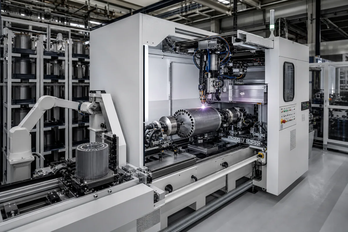
Electric motor rotor lamination stacking and welding machine
Machines that stack and weld electrical steel laminations into motor cores · Expanding welding arbors that align the stack, axial welds on the outer surface, arbor storage and changeover between core sizes, weld seams on rotor teeth, and alternatives to welding
A lamination stacking and welding machine builds the magnetic core of a motor rotor or stator from thin electrical steel laminations: it stacks them to height, aligns them on a mandrel (arbor), clamps the stack and welds it so the core can be handled as one piece. Ask three things first: which core sizes and stack heights it must make, how the stack is aligned and clamped, and where the welds go and how changeover between core types is handled.
Machines and cells that stack electrical steel laminations and join them by welding into rotor or stator cores, including arbors, clamping, welding heads and arbor storage. Lamination stamping presses, interlocked or bonded cores without welding, winding machines and finished lamination stacks (see electric motor stator lamination stack) are outside this page except where compared.
CNFX editorial research · Sources checked October 12, 2026 · 4 sources
US patent 6,046,432 (Apparatus for welding lamination stack to produce core of electromechanical machine, 2000) describes the established method: a large number of laminations are stacked on a welding arbor to the desired height; the welding arbor is configured to expand radially against the inner circumference of the stack so the laminations are concentrically aligned; and a welding device makes vertical welds (at least six in the patent's apparatus) at set angular positions on the outer circumference so the laminations become a core body that can be handled as a unit. [1]
US patent 6,301,773 B1 (Method of manufacturing a motor core, 2001) notes that "motor cores are generally composed of many layers of thin metal plates", fastened with welds, rivets or bolts that hold and/or compress the layers, and that annealing forms an oxide layer that insulates adjacent plates provided they are not under significant compression; its own method bonds layers with adhesive without compression for loosely laminated stacks. [2]
Editorial note: tell the supplier whether your core is welded, interlocked or bonded, and ask how weld position and heat input affect the core's insulation and losses.
Give the supplier the core types (rotor or stator), outer and inner diameters, slot or tooth geometry, stack height range and tolerance, lamination thickness and grade, alignment features (keyways, skew), weld count, positions and length, welding process, clamping force, cycle time and output, number of core variants and changeover time, lamination feeding (from press or magazine), and inspection of height, weight and weld quality.
02
Plan arbor changeover and weld seam positions
US 6,046,432 explains that core dimensions such as outer diameter, inner diameter and slot spacing depend on the motor, and that "typically, a different welding arbor will be required for each of the various core configurations"; it says earlier systems made it difficult "to store and retrieve the different arbors without delays in the manufacturing process". Its apparatus keeps arbors at storage locations, uses a transporter to move each arbor to and from storage, and a conveyor to move arbors between the transporter and the welding device. [1]
US patent 12,278,522 B2 (Welding of a stack of laminations for a rotor, 2025) concerns wound (separately excited) rotors for electric and hybrid vehicles, where the rotor body is a lamination stack with radial teeth carrying field coils. It notes that press-fitting the rotor body on its shaft can move laminations relative to one another, leading to premature rotor failure or poorer balance, and places at least one weld seam on a lateral face of a tooth, extending radially and axially. [3]
Editorial note: ask the supplier where its weld seams can be placed for your rotor geometry, and how stack alignment is kept through welding and later press-fitting.
03
Ask how the machine controls heat input along the weld bead
A patent filed by lamination maker Mitsui High-tec (US 10,424,995 B2, priority 2015) covers a welding machine for laminated cores whose torch travels along the side of the stack in the stack-height direction under a controller that varies heat input. It reports that when a bead running the full height of the stack was welded under the same condition from start to finish, cracks appeared at the centre of the bead, where it says stress is highest. Raising heat input at the centre of the bead relative to its ends, either by changing the welding current midway or by slowing the torch, brought the occurrence of weld cracks to 0% in its examples. Its penetration-area reference condition is a welding current of 115 A at a welding speed of 5 mm/s; penetration area rises with higher current or lower speed. [4]
The same patent gives the core context: electromagnetic steel sheet of approximately 0.1–0.5 mm, with 0.1–0.3 mm preferred for better magnetic characteristics, strip widths of approximately 50–500 mm, stator yoke widths of approximately 2–40 mm depending on the motor, laminates held under compression between welding tools while welded, and, as an alternative to one continuous bead, intermittent beads of approximately 5–20 mm length, each with more heat at its centre. [4]
Editorial note: this complements the arbor-based apparatus of US 6,046,432; ask the supplier whether its welding heads can vary current or travel speed along each bead, how many beads it welds per pass, and what crack inspection it applies after welding. [4][1]
Core diameter, stack height, cycle time and welding power for a stacking and welding cell
None of the reviewed patents gives machine ratings such as cycle time, welding power or footprint; the diameter and stack height rows follow from your core drawings, and the 115 A, 5 mm/s condition in Mitsui High-tec's patent is the only published welding figure. [4]
Explore company information and manufacturing capabilities, then discuss the scope of your project with a relevant supplier.
Share this page
Compiled and source-reviewed by the CNFX editorial team.
Each manufacturer above links to the page on that company's own website where the product is listed, with the date we checked it. How we source and review
· Page last updated 13 October 2026
Buyer questions
How are lamination stacks welded into cores?
Laminations are stacked on an arbor that expands in the bore to align them, then welded with vertical seams at set positions on the outer surface (US 6,046,432). [1]
Why does changeover matter?
US 6,046,432 says "a different welding arbor will be required for each of the various core configurations"; storing and retrieving arbors quickly avoids delays (US 6,046,432). [1]
Where else can rotor stacks be welded?
US 12,278,522 places seams on the side faces of wound-rotor teeth to stop laminations shifting during press-fitting. [3]
Why do weld beads on lamination stacks crack, and how is it prevented?
Mitsui High-tec's patent US 10,424,995 B2 reports cracks at the centre of full-height beads welded under one constant condition, and 0% cracks when heat input at the bead centre was raised by increasing current or slowing the torch, from a 115 A, 5 mm/s reference. [4]
Sources and what still needs a direct check
Sources checked 2026-10-12. All four sources are US patents (2000, 2001 and 2025, plus one with a 2015 priority date) that describe core stacking and joining in their own terms.