Pump impellers · Trimming and affinity laws, minimum diameter, NPSHR, wear-ring clearances and replacement
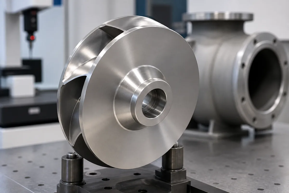
A centrifugal pump impeller is the vaned rotor, open or closed, that spins inside the casing and adds energy to the liquid; its diameter, vane design and the clearances at its wear rings set the head, flow and efficiency the pump delivers. Ask three things first: the diameter and trim range that match your duty on the maker's curve, the wear-ring arrangement and clearances, and the material and balancing for your liquid and speed.
Impellers for centrifugal pumps, open, semi-open and closed, as new or replacement parts, including trimmed impellers. Complete pumps, positive-displacement rotors, blower and turbocharger wheels, and motor rotors are outside this page.
CNFX editorial research · Sources checked October 12, 2026 · 4 sources
The US Department of Energy's pumping tip sheet No. 7 (2006) recommends trimming when an oversized, throttled pump delivers more head than needed, bypass valves are open or the pump runs far from its design point. Trimming should be limited to about 75% of the pump's maximum impeller diameter and never below the minimum diameter on the maker's curve, because the added clearance to the casing increases recirculation and head loss and lowers efficiency. DOE's impeller-trimming tip sheet links impeller size to the NPSHR at a given flow rate, so check with the manufacturer first. [1]
Where curves are not available, DOE gives the affinity laws for diameter change: Q₂/Q₁ = D₂/D₁, H₂/H₁ = (D₂/D₁)² and bhp₂/bhp₁ = (D₂/D₁)³. Its example trims a 14 in impeller on a 3,000 gpm pump from 165 ft to 125 ft of head: D₂ ≈ 14 × (125/165)^(1/3) ≈ 12.76 in, cutting power from 156 to about 118.4 bhp at 80% efficiency, saving about 238,720 kWh a year over 8,000 hours with a 94% efficient motor. DOE advises consulting the maker before changing mixed- or axial-flow impellers. [1]
Editorial calculation: 12.76/14 ≈ 0.91, so this trim is about 91% of the original diameter, well above the 75% limit DOE suggests.
Give the supplier the pump make, model and casing, current impeller diameter and drawing, required flow and head, speed, liquid and temperature, solids content, wear-ring arrangement, material, balancing grade and whether the impeller is to be trimmed or replaced.
02
Check what a measured trim did to one pump before relying on the affinity laws
A 2021 Jiangsu University study in Entropy trimmed the impeller of a double-suction centrifugal pump with a design flow of 500 m³/h at 1480 r/min and a specific speed of 24 (European definition). The original impeller had a 365 mm outlet diameter, 46 mm outlet width, 6 blades and a 29.5° blade outlet angle. The authors report that trims made by the pump's manufacturer did not give the performance the empirical equations predicted. [4]
The impeller was trimmed at constant radius by 11, 22 and 33 mm. In tests on the original and the 11 mm trim, the head predicted by a corrected empirical equation for double-suction pumps, H′/H = (D′₂/D₂)^(1/0.42), was within 4.6% of the test at 0.2 Qd, but the deviation grew to 5.1% at Qd and 37.2% at 1.4 Qd, because the head dropped more than expected. The best efficiency point moved from 550 m³/h to 500 m³/h. The authors trace the loss to the volute: the trimmed impeller raised the incidence angle at the volute tongue and increased flow separation at overload. Predicted power matched the tests at all flow rates studied, and radial forces decreased in every case investigated. [4]
Editorial calculation: for the 11 mm trim, 354 ÷ 365 ≈ 0.970. DOE's square law gives 0.970² ≈ 0.941 of the original head, and the corrected equation gives 0.970^(1/0.42) ≈ 0.930, so even before the measured overload error the two predictions differ by about one percentage point of head. The deepest trim, 332 ÷ 365 ≈ 0.91, sits well above DOE's 75% limit, which shows that staying within that limit does not by itself protect efficiency at overload. Ask the supplier for a tested curve of the trimmed impeller in your casing, not only a calculated one. [1][4]
EASA's Gene Vogel, writing in Pumps & Systems (2019), explains that suction-side wear rings limit leakage from discharge back to suction, so excessive clearance costs volumetric efficiency, while rear rings with balance holes limit axial thrust, so excessive clearance can overload the thrust bearing. Clearances matter more for low-specific-speed impellers, where leakage is a larger share of flow. [2]
Where the manufacturer's tolerances are unavailable, the article gives new wear-ring clearances for water service of 0.010 in plus 0.002 in per inch of diameter up to 5 in, and 0.015 in plus 0.001 in per inch from 5 to 10 in, adding 0.005 in for galling materials; or the API 610 (ISO 13709) chart of minimum running clearances for 50–650 mm rings, which specifies minimums because tighter clearances risk contact and failure. Clearances are diametral, so running clearance is half the stated value, and some manufacturers recommend replacement when clearance has grown 40% beyond the original. [2]
Editorial calculation: a 4 in ring gets 0.010 + 4 × 0.002 = 0.018 in diametral (about 0.46 mm), i.e. 0.009 in radial; at 40% wear it would reach about 0.025 in. [2]
04
Cast-iron, sand-pump and machined impellers on the listed sites
Listings include cast-iron and sand-pump impellers with open and closed vanes, and machined impellers among CNC and cast parts.
05
Specify the balance grade and how the impeller will be balanced
The Hydraulic Institute (HI) warns that high residual unbalance in rotating parts generates unbalance forces that overload bearings and shaft and induce high vibration. Its reference practice for pump impellers is ISO 1940 balance quality grade G6.3 or better. The allowable value is read from the G6.3 chart at the maximum expected service speed: at 3000 rpm HI reads 0.021 kg-mm/kg (0.85 oz-in/oz), and multiplying by the impeller weight gives the allowable unbalance in kg-mm. For slurry-pump impellers HI refers buyers to the latest edition of ANSI/HI 9.6.4. [3]
HI states that a single-plane spin balance may be satisfactory when the impeller's diameter-to-width ratio D/b is 6.0 or greater; otherwise two-plane (dynamic) balancing is performed. The balancing machine must be able to measure unbalance down to one tenth of the maximum residual unbalance allowed by the selected grade, and because the allowable value comes from the chart, the machine does not need to run at pump speed. [3] Editorial calculation: a 10 kg impeller for 3000 rpm service at G6.3 would be allowed 0.021 × 10 = 0.21 kg-mm (210 g-mm) of residual unbalance, and the balancing machine would need to resolve 0.021 kg-mm. Ask the supplier to state the grade, the speed used to read the limit, the number of balancing planes and the measured residual unbalance on the balancing report, and re-check balance after any trim.
06
Diameter, vanes, wear rings and hub: what to fix on the drawing
Trim diameter, balance grade and material for a replacement impeller
Diameter is bounded by DOE's trimming limit and material by EASA's added ring clearance for galling alloys; vane angle, hub and surface roughness come from the pump's hydraulic drawing.
Field
What it means and published values
Ask the supplier for
Diameter (mm)
Not below curve minimum or about 75% of maximum. [1]
Diameter and trim.
Number of vanes (count)
Hydraulic design.
Count and type.
Hub diameter (mm)
Shaft fit.
Dimension.
Vane angle (degrees)
Hydraulic design.
Drawing.
Maximum RPM (rpm)
Pump speed.
Rated speed.
Balance grade (G-level)
Running smoothness.
Grade and report.
Operating pressure (MPa)
Casing pressure.
Rating.
Operating temperature (°C)
Liquid temperature.
Range.
Material
Galling materials need +0.005 in ring clearance. [2]
Material and certificate.
Surface roughness (μm)
Hydraulic passages.
Finish.
Weight (kg)
Handling and balancing.
Weight.
08
Send the pump, duty and impeller data together
Paste it into your enquiry below or into an email to a maker, then replace every bracket.
Tianjin Geostar lists cast-iron and sand-pump impellers; Vigor Inno-Tech lists impellers among CNC-machined and cast parts; Hulk Metal lists lost-wax cast steel pipeline pump impellers.
Tianjin Geostar Petroleum Equipment Co., Ltd.
Manufacturing site to be confirmed for the order
Lists cast-iron centrifugal pump impellers and open- and closed-vane sand pump impellers.
Explore company information and manufacturing capabilities, then discuss the scope of your project with a relevant supplier.
Share this page
Compiled and source-reviewed by the CNFX editorial team.
Each manufacturer above links to the page on that company's own website where the product is listed, with the date we checked it. How we source and review
· Page last updated 13 October 2026
Buyer questions
How much can an impeller be trimmed?
DOE suggests limiting trimming to about 75% of the maximum impeller diameter and never below the minimum on the maker's curve. [1]
How do flow, head and power change with impeller diameter?
By the affinity laws DOE cites: flow with diameter, head with its square and power with its cube. [1]
What wear-ring clearance should a new impeller have?
Use the maker's tolerance; otherwise EASA gives 0.010 in plus 0.002 in per inch of diameter up to 5 in for water service, or the API 610 minimums. [2]
What balance grade should a replacement pump impeller meet?
The Hydraulic Institute gives ISO 1940 grade G6.3 or better for pump impellers, with the limit read at the maximum service speed (0.021 kg-mm per kg of impeller weight at 3000 rpm); single-plane balancing may be satisfactory when D/b is 6.0 or greater. [3]
Do the affinity laws predict head accurately after trimming?
Not always. In a 2021 study of a double-suction pump trimmed from 365 mm to 354 mm, the corrected empirical equation was within 4.6% at 0.2 Qd but 37.2% off at 1.4 Qd; ask for a tested curve. [4]
Sources and what still needs a direct check
Sources checked 2026-10-12. DOE's tip sheet is US government guidance (2006); the wear-ring guidance is from EASA, a repair-industry association, published in Pumps & Systems, and the balance guidance from the Hydraulic Institute. A 2021 Jiangsu University study in Entropy reports measured effects of trimming on one double-suction pump. Manufacturer curves and tolerances take precedence.