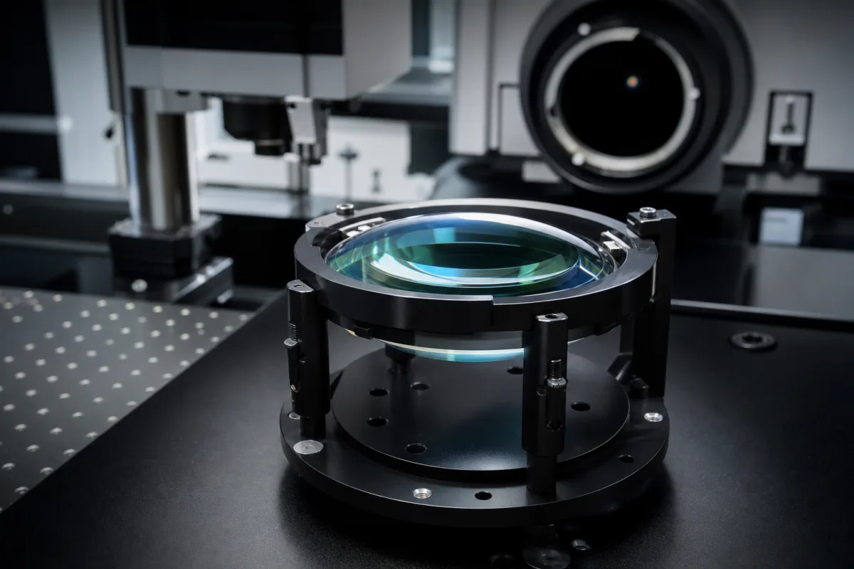
Aspheric optics · Polished vs molded, materials, radius and irregularity tolerances, mid-spatial errors and slope, wedge and decenter
A precision aspheric lens has at least one surface whose curvature changes from centre to edge, so a single element can cut aberrations that would otherwise need two or more spherical lenses. Ask three things first: whether it will be CNC-polished, precision glass-molded or made another way, which material and coating your wavelength and power need, and how form, slope, centration and surface quality will be toleranced and measured.
Aspheric lens elements in glass, fused silica, crystals and infrared materials, polished or molded, for imaging, illumination and laser systems. Complete lens assemblies, spherical lenses, freeform optics and plastic injection-molded lens arrays are outside this page.
CNFX editorial research · Sources checked October 11, 2026 · 4 sources
In Laser Focus World (2015), Edmund Optics authors describe CNC-polished aspheres ground and polished one at a time with small tools, optionally corrected by magnetorheological finishing (MRF). Costs are driven by machine time with little economy of scale, but lead times are short, prototypes and production are made the same way, and almost any substrate can be used, from optical glasses to fused silica, calcium fluoride, germanium, zinc selenide and chalcogenide glass. [1]
The same article describes precision glass molding as the dominant technology for laser-diode collimators since the early 1980s: an isothermal compression of a glass preform between compensated molds in nitrogen, giving thousands of low-cost replicas once the mold is made. Its drawbacks are high initial tooling cost, long lead times to correct the mold for glass shrinkage, and materials limited to glasses with relatively low transformation temperatures. [1]
Editorial note: for laser use the article ties the choice to the laser's energy and wavelength; give both to the supplier with your quantity, since they decide which process and material are viable.
Give the supplier the wavelength band and laser power if any, focal length and aperture, the asphere prescription (vertex radius, conic, coefficients) or sag table, material, centre thickness, clear aperture, coating, tolerances, quantity and inspection data required.
02
Follow a precision glass molding cycle step by step
Eastman Kodak's US patent 3,833,347 (filed 12 March 1973 as a continuation of a 27 November 1970 application, granted 3 September 1974) presses a glass preform into finished image-forming lenses — spheres or aspheres — between mould inserts of glasslike carbon, a chemically inert, isotropic carbon made by thermally degrading an organic polymer; the inserts are dimensioned and polished to the accuracy and surface quality the lenses must have. [3]
Its worked example runs this cycle: evacuate the chamber to about 100 microns of pressure while induction-heating the mould to 200–300 °C to outgas the carbon; admit a nitrogen forming gas with 5 percent hydrogen at a slight overpressure; heat the mould to 700–800 °C, near the glass softening point, and hold one to five minutes with the upper insert close to the softened glass; apply the load and cool to 550–600 °C, below the glass's 622 °C transformation point, keeping glass and mould at equal temperature under load to prevent distortion; then remove the load and cool to 300 °C before opening, to stop the carbon and graphite oxidising. [3]
The patent reports lenses with radii of 11 mm on one side and 86 mm on the other that were essentially strain-free, so no further annealing was needed, and contrasts this with the prior route for precise aspheres, where grinding adjustments had to be made by hand. [3] Editorial calculation: the example cools the loaded mould from 700–800 °C to 550–600 °C, a drop of 100–250 °C under load; this is the step where the mould must be compensated for glass shrinkage, which the Laser Focus World article names as a reason for long mould lead times. [3][1]
A 2025 study from Guizhou University and Hunan University's National Engineering Research Center for High Efficiency Grinding (Shu et al., iScience) shows how far a molded asphere departs from its mould and how the mould is corrected. Molding K-LCV161 glass (transformation temperature Tg 426 °C, yield temperature 469 °C), simulation predicted a lens form error of PV 7.187 μm from cooling shrinkage and glass/mould thermal expansion; pre-compensating the mould profile brought the molded lens to PV 0.6186 μm, and a second, higher-order compensation from measured lenses brought it to PV 0.1525 μm. The authors set PV ≤ 0.3 μm as the form accuracy an asphere of about 20 mm effective diameter needs. The final tungsten carbide mould was ground to PV 90.2 nm and Ra 3.723 nm and given a 128 nm ta-C coating; seven lenses pressed at 495 °C, 0.25 MPa and a 1 °C/s annealing cooling rate measured PV 0.2168 ± 0.036 μm and Ra 4.923 ± 1.53 nm. [4]
Editorial calculation: 7.187 / 0.1525 ≈ 47, so the two compensation steps cut form error by a factor of about 47; the lens roughness (Ra about 4.9 nm) stayed above the mould's 3.7 nm, consistent with the paper's statement that the mould's surface sets the lens surface. For a molded asphere, ask the supplier for the mould material and coating, how many compensation iterations the mould has had, and measured PV and Ra on production lenses, not only on the mould. [4]
03
Tolerance radius, irregularity, slope and centration
In an Edmund Optics article on tolerancing aspheres, the authors say aspheric lenses should be toleranced only with a linear radius tolerance, not fringes of power, because power assumes a constant radius of curvature; that the conic constant and aspheric coefficients should not be toleranced, with radius and irregularity tolerances controlling permissible form error; and that mid-spatial-frequency ripple, which sub-aperture tools can leave, is best controlled with a slope-error specification over a stated integration length. [2]
They note that aspheres cannot be re-centred after fabrication as spheres can, and that wedge should be characterised as both aspheric tilt and lateral decenter rather than by beam deviation alone. Clear aperture should be given in linear units, with aspheres processed oversize for tool run-off; an aspect ratio around 6:1 (diameter to centre thickness) is described as ideal; and a scratch-dig surface quality of 60-40 is, described by the authors as acceptable except for short-wavelength or high-power systems, specified to ANSI/OEOSC/ISO 10110-7:2017. [2]
Editorial calculation: at the 6:1 aspect ratio cited, a 25 mm diameter asphere would have a centre thickness of about 4.2 mm. [2]
04
Laser and imaging aspheres, silicon infrared aspheres and mixed optics catalogues
Listings include precision aspheric lenses for laser and imaging use, silicon and other infrared aspheres, and aspheric lenses among spherical lenses, prisms, windows and domes.
05
Prescription, substrate, process route, form and slope, centration and coating
Centration has to be set on the drawing rather than corrected later: Edmund Optics notes that an asphere cannot be re-centred after fabrication the way a sphere can. [2]
Element
Role
Fix in the order
Aspheric prescription
Vertex radius, conic, coefficients or sag table. [2]
Focal length, clear aperture, centre thickness, form accuracy and scratch-dig for an asphere quotation
Surface accuracy here means irregularity plus a slope-error limit over a stated integration length, the way Edmund Optics controls mid-spatial ripple, rather than an RMS figure alone. [2]
5 companies list this product among what they make. Company figures are quoted from each
company's own website; every card states where the relationship came from.
Alhazen
Manufacturing site to be confirmed for the order
Lists precision aspheric lenses for laser use among lenses and domes.
Explore company information and manufacturing capabilities, then discuss the scope of your project with a relevant supplier.
Share this page
Compiled and source-reviewed by the CNFX editorial team.
Each manufacturer above links to the page on that company's own website where the product is listed, with the date we checked it. How we source and review
· Page last updated 13 October 2026
Buyer questions
How should an aspheric surface be toleranced?
Edmund Optics engineers recommend a linear radius tolerance and irregularity, not fringes of power, and not tolerancing the conic or aspheric coefficients. [2]
Should an asphere be polished or molded?
CNC polishing suits prototypes, small volumes and almost any material; precision glass molding suits volume production of low-Tg glasses after a costly mold. [1]
How are mid-spatial frequency errors controlled?
With a slope-error specification over a defined integration length. [2]
What temperatures does precision glass molding of lenses use?
In Kodak's US patent 3,833,347 example the mould is heated to 700–800 °C, pressed and cooled under load to 550–600 °C, below the glass's 622 °C transformation point. [3]
How accurate can a precision-molded glass asphere be?
Shu et al. (iScience, 2025) report molded K-LCV161 aspheres of PV 0.2168 ± 0.036 μm form accuracy, best 0.1525 μm, after two rounds of mould compensation, against a predicted 7.187 μm without it. [4]
Sources and what still needs a direct check
Sources checked 2026-10-11. Two sources are written by Edmund Optics engineers, an optics maker, in trade publications; the Eastman Kodak patent describes its own glass molding process; ISO 10110 governs drawing conventions. A 2025 iScience paper from Guizhou and Hunan universities reports measured form errors of molded aspheres before and after mould compensation.