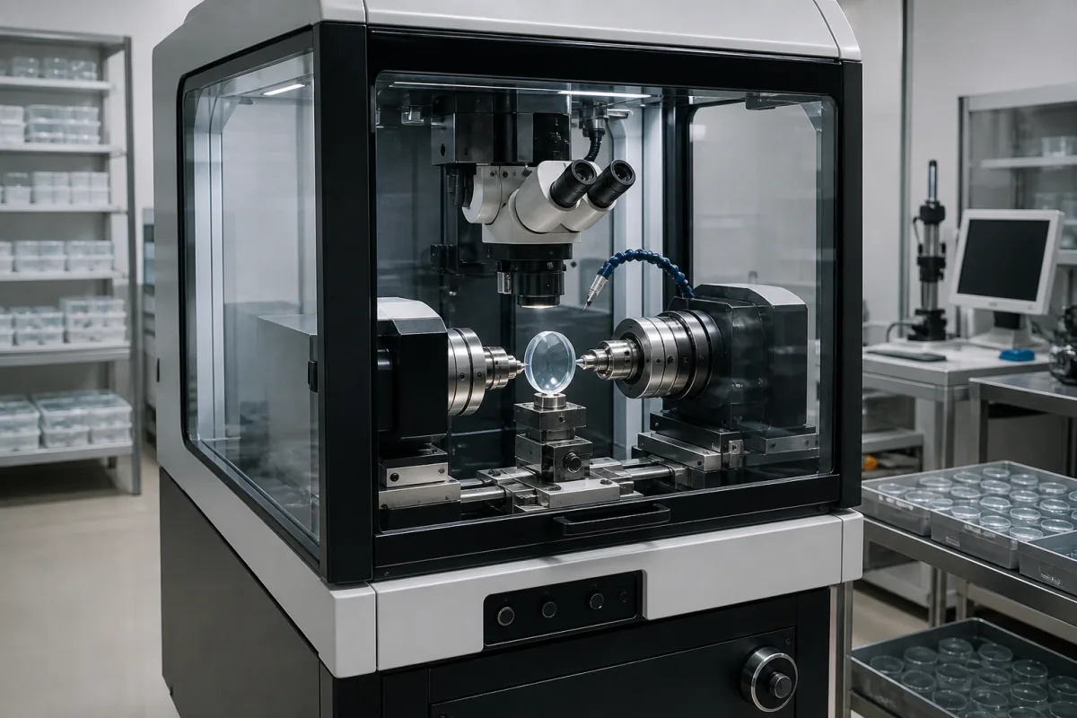
Precision optical lens centering machine (bell-clamp centering and edging)
Bell-clamp centering and edging · Two coaxial spindles align the polished lens on its optical axis, then a wheel grinds the edge round to it
A lens centering machine works on a lens whose two optical surfaces are already polished. It clamps the lens between two hollow bells on coaxial spindles; the curved surfaces slide in the bells until the lens's optical axis lies on the spindle axis. A grinding wheel then cuts the edge, bevels and steps around that axis, so the outer diameter that will sit in the mount is centred on the optics. The questions are lens size, how strongly curved the surfaces are, and how the result is checked.
CNC and manual centering machines that clamp polished spherical and aspherical lenses between centering bells (or on blocked arbors) and grind the edge, bevels, recesses and chamfers concentric to the optical axis, with their laser or optical centering aids. Machines that generate and fine-grind the optical surfaces themselves are covered on the Precision optical lens grinding machine page, and surface polishers on the Precision optical lens polishing machine page. Centration test systems and interferometers are covered on the Precision optical lens inspection and measurement system page; one such instrument appears here only as the reference for checking an edged lens. Ophthalmic spectacle-lens edgers are outside this page.
CNFX editorial research · Sources checked October 12, 2026 · 4 sources
Bell clamping, Hydro-Soft centering and lenses with a small centering angle
OptoTech describes its ZM machines as bell-clamping centering machines: the lens is held between the top and bottom centering spindles, which on the ZM 200 CNC-TC are Ø60h4 × 300 mm. The maker attributes precise centering, "even for small centering angles", to its Hydro-Soft bell clamping method. [1]
When the surfaces are only slightly curved, clamping alone is not enough. Both the ZM 200 and ZM 50 CNC-TC offer a laser centering device working in transmission and reflection for lenses with a small clamping angle, and the ZM 50 adds laser centering software for aligning low-aperture lenses. Blocked lenses can be centred instead on an interchangeable arbor. [1][2]
Clamping force matters as much as alignment. On the ZM 50 CNC-TC the clamping spindle (W-axis) has servo control of clamping force and position, which OptoTech says allows repeatable setting of very low clamping forces, higher stock removal and no marks from the centering bells. [2]
Editorial note: the clamping angle comes from the lens design (its radii and the bell diameters), not from the machine. Send the lens drawing with both radii and the finished diameter so the supplier can say whether bell clamping alone will centre it or whether the laser aid or a blocked arbor is needed.
Give both radii of curvature, the centre thickness, the finished diameter and bevels, the centring tolerance on the drawing, the glass type and coating, and whether the lens arrives loose or blocked.
02
From 0.5 mm endoscope lenses to 300 mm optics: three machine classes
Lens diameter sets the machine class. OptoTech's three centering machines below span 0.5 mm to 300 mm; the micro-optics machine also takes rods and plano optics. [3][2][1]
The two larger machines carry two tool spindles (TwinCut) working simultaneously, for which OptoTech claims cycle-time savings of up to 30–40%, and they measure centre thickness to correct the program automatically. The DZM 20 has a horizontal axis arrangement and a workspace that opens automatically for manual or automated loading; it uses one CNC cross slide with a Ø120 mm centering wheel plus a clamping axis that measures and compensates centre thickness. [1][2][3]
Editorial calculation: on the ZM 200, a Ø200 mm wheel at the maximum 5,600 rpm would run at π × 0.2 m × 5,600 / 60 ≈ 58.6 m/s, above the stated 30 m/s cutting-speed ceiling, so that wheel is limited to about 2,860 rpm; a Ø120 mm wheel reaches 30 m/s at about 4,770 rpm. The spindle speed alone does not show the usable range. [1]
State the smallest and largest lens diameter, the maximum lens height, the edge geometry (bevel angles, steps, recesses), and whether loading is manual, by disk magazine or by robot.
03
Checking centration after edging: 0.1 µm reflection measurement
A centered edge is verified on a separate instrument. Trioptics specifies its OptiCentric Compact for measuring the centration of single lenses with respect to the lens edge, using a motorized lens rotation device, at a measurement accuracy for centration in the visible range of < 0.1 µm, for samples up to 120 mm as standard and 200 mm as an option. [4]
Trioptics lists the Compact as a 36 kg table-top unit of 820 × 850 × 400 mm, ISO 5 cleanroom compatible. A version with a manually driven rotary air bearing, the Compact AB, takes samples up to 280 mm and 20 kg and is aimed at lens bonding and cementing. [4]
Editorial note: the measuring instrument's accuracy is not the machine's centring tolerance. Neither OptoTech data sheet reviewed here states a centring tolerance in µm or arcseconds, so ask the machine supplier for measured results on a lens like yours and agree how they will be checked.
04
Lens data for a centering machine quotation
Paste it into your enquiry below or into an email to a maker, then replace every bracket.
Lens: [diameter range; R1 and R2; centre thickness; glass; coated or not]
Edge: [finished diameter and tolerance; bevels; steps; recesses]
Centring tolerance: [as on drawing, µm or arcsec]
Clamping: [loose lens in bells or blocked on arbor]
Volume: [lenses per shift; loading method]
Acceptance: [measurement method and instrument]
Explore company information and manufacturing capabilities, then discuss the scope of your project with a relevant supplier.
Share this page
Compiled and source-reviewed by the CNFX editorial team.
Each manufacturer above links to the page on that company's own website where the product is listed, with the date we checked it. How we source and review
· Page last updated 13 October 2026
Buyer questions
What does a lens centering machine do?
It clamps a polished lens between two coaxial bells so its optical axis aligns with the spindle axis, then grinds the edge concentric to that axis. [1]
What if the lens surfaces are only slightly curved?
Lenses with a small clamping angle may not self-centre; OptoTech offers a laser centering device in transmission and reflection for them, or centering of blocked lenses on an arbor. [1][2]
What lens sizes do centering machines cover?
In OptoTech's range, 0.5–20 mm on the DZM 20 for micro-optics, up to 80 mm on the ZM 50 and 10–300 mm on the ZM 200. [3][2][1]
How is the centring checked?
On a centration measuring instrument; Trioptics specifies its OptiCentric Compact at < 0.1 µm for centration in the visible range. [4]
Sources and what still needs a direct check
Sources checked 2026-10-12. Machine data are from three OptoTech technical data sheets, each marked as subject to change; the measurement figures are from Trioptics' own data sheet and brochure. They describe single products, not a class standard.