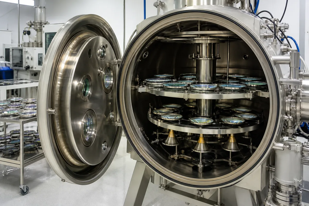
Box-type vacuum evaporation coaters for anti-reflective and filter coatings on lenses and optical components · chamber and calotte size, lens loading, ultimate vacuum and pump-down time, electron-beam and thermal sources, ion or plasma assistance, quartz crystal and optical monitoring, substrate heating
An optical lens coating chamber is the vacuum chamber of a box coater, with its pumps, evaporation sources, ion or plasma source, substrate holder (calotte), heaters and thickness monitors, in which anti-reflective, mirror and filter coatings are deposited on lenses and other optical components. Ask three things first: how many lenses of your diameter one calotte holds and what chamber size that needs; the vacuum and pump-down time the pumping system reaches; and how the layers are evaporated, assisted and monitored.
Batch (box) vacuum evaporation coaters and their chambers for optical lenses and precision optical components, with electron-beam and thermal evaporation, ion or plasma assistance, quartz crystal and optical thickness monitoring and substrate heating. Ion-beam sputtering and magnetron sputtering systems, inline architectural or display glass coaters, ophthalmic hard-coat dip or spin lines, and coating materials are outside this page except where compared.
CNFX editorial research · Sources checked October 11, 2026 · 5 sources
Lens coaters are sized by the calotte (dome substrate holder) and how many lenses of a given diameter it carries. OptoTech's smallest coater, the OAC-25F, has a 370 mm calotte holding 96 lenses of Ø 18 mm, 35 of Ø 50 mm or 16 of Ø 70 mm, in a stainless steel vacuum chamber with an electro-polished surface, pumped by a turbo pump and pre-pump with a Meissner trap. [2] The OAC-90F has an 850 mm calotte holding 168 lenses of Ø 40 mm, 90 of Ø 70 mm or 21 of Ø 120 mm, with a cryo pump and turbo or diffusion pumps as options. [1] Bühler Leybold Optics offers its SYRUSpro coaters in eight chamber sizes with inner diameters between 710 mm and 2,800 mm, chosen to match loading capacity and substrate size. [4]
Chengdu Guotai's ZZS920 optical coating machine specification lists a Φ920 mm × H1,000 mm chamber with a Φ850 SR700 workpiece plate, an ultimate vacuum of 4 × 10⁻⁴ Pa, a pump-down time to 4 × 10⁻³ Pa of less than 15 min, and a pumping system of diffusion pump, two-stage rotary vane pump and Roots pump; the maker lists other models from ZZS500 to ZZS2350. [3]
Editorial calculation: 1 mbar = 100 Pa, so 4 × 10⁻⁴ Pa is 4 × 10⁻⁶ mbar and 4 × 10⁻³ Pa is 4 × 10⁻⁵ mbar. [3]
Give the supplier the lens or component diameters and shapes (flat, convex, concave radii), lenses per batch and batches per day, the coatings (AR, HR, filters) and spectral range, substrate materials and their maximum temperature, required ultimate vacuum and pump-down time, pump type (cryo, turbo, diffusion with Polycold), chamber material and finish, utilities (power, cooling water, compressed air) and floor space.
02
Choose evaporation sources, ion assistance, monitoring and heating
OptoTech's OAC-90F lists up to three electron-beam evaporation sources for simultaneous operation, a thermal evaporation source, an ion source or optional plasma source, an IR-heating system and thin-film deposition control by the quartz crystal method, with a broadband optical monitor (indirect measurement) as an option. [1] The Guotai ZZS920 combines resistance evaporation with two 5 kW electron guns, film thickness control with an SQC310 quartz crystal controller using a single or six-point crystal probe, and heating to a maximum of 350 ℃. [3]
A dual-e-gun coater described by National Tsing Hua University gives source and monitor figures in detail: e-guns of up to 10 kV, 1 A and 10 kW with 15 crucibles of 12 ccm, an End-Hall ion gun of up to 200 V and 5 A for assisting and cleaning, four quartz sensors plus an optical thickness monitor covering 360 to 1,000 nm with 38 monitor glasses, tubular electric heaters reaching up to 250 °C, and a substrate holder up to 800 mm in diameter; Ar, O2 and N2 can be added during deposition. [5]
Bühler lists in-situ optical monitoring, plasma sources, electron-beam and thermal evaporators, quartz crystal measurement and substrate holder systems as configurable components of the SYRUSpro. [4]
Editorial note: ask each supplier whether layer thickness is cut off by quartz crystal rate control, by optical monitoring, or both, and on which witness glass or substrate the optical monitor measures, because this decides layer-thickness accuracy for multilayer AR and filter designs.
03
Loading tables, pump-down times and measured spectra per coater offer
When requesting quotations, ask each supplier for calotte loading tables for your lens diameters, ultimate vacuum and pump-down time with the pumps offered, source, ion-source and monitor configurations, heating range, sample coatings with measured spectra, and installation plans.
04
Pumps, calotte, sources and monitors inside a lens coater
Element
Role
Fix in the order
Vacuum chamber
Stainless steel, electro-polished; Φ920 × 1,000 mm example. [2][3]
Size, material.
Pumping system
Cryo, turbo or diffusion pump; Meissner trap, Polycold. [1][2][3]
Pumps, times.
Calotte
Dome substrate holder, 370 to 850 mm on OptoTech coaters. [2][1]
Diameter, loading.
Evaporation sources
E-beam guns and thermal (resistance) sources. [1][3]
Guns, crucibles.
Ion or plasma source
End-Hall ion gun or plasma source for assistance and cleaning. [5][1]
IR or tubular heaters; to 250 or 350 °C. [1][5][3]
Max temperature.
05
Chamber size, vacuum and thickness control for a coater RFQ
Leak rate, coating uniformity, ports and power supply are not stated in any reviewed source, so those rows carry only what to ask; chamber size, ultimate pressure and lens loading have published examples.
Explore company information and manufacturing capabilities, then discuss the scope of your project with a relevant supplier.
Share this page
Compiled and source-reviewed by the CNFX editorial team.
Each manufacturer above links to the page on that company's own website where the product is listed, with the date we checked it. How we source and review
· Page last updated 13 October 2026
Buyer questions
How many lenses does an optical coater calotte hold?
OptoTech's OAC-90F 850 mm calotte holds 168 lenses of Ø 40 mm, 90 of Ø 70 mm or 21 of Ø 120 mm. [1]
What vacuum does an optical evaporation coater reach?
Guotai's ZZS920 lists 4 × 10⁻⁴ Pa ultimate vacuum and under 15 minutes to reach 4 × 10⁻³ Pa. [3]
How is layer thickness controlled during lens coating?
By quartz crystal monitors and optical monitors; one university coater uses four quartz sensors and a 360–1,000 nm optical monitor. [5]
Sources and what still needs a direct check
Sources checked 2026-10-11. The sources are two OptoTech coater datasheets, a Chengdu Guotai coater specification, a Bühler Leybold Optics product page and a university coating-facility page.