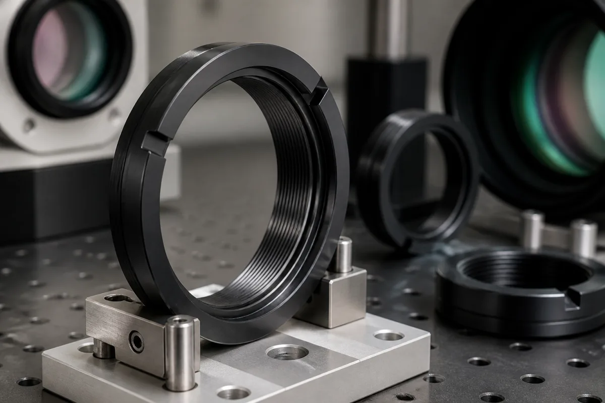
Threaded lens retaining rings for optical barrels and cells · Retaining ring versus burnished and elastomer mounts, preload from lens mass and shock level, square, tangent and spherical contacts, axial contact stress, thermal clearance, spanner slots and thread fit
A precision optical lens mounting ring, or retaining ring, is a threaded ring that screws into a lens barrel or cell and presses the lens against its seat, fixing it axially; it is tightened with a spanner in its slots to a set torque that gives the preload the shock and vibration environment needs without overstressing the glass. Ask three things first: what lens diameter, mass and shock level the ring must hold, which contact shape and preload the lens surface and glass can take, and what thread, material, finish and tightening method the barrel and assembly use.
Threaded retaining rings, lock rings and spacer rings that hold lenses, windows and filters in optical barrels and cells, including standard thread series and custom rings. Complete lens barrels and mounts, external snap rings and circlips (see external retaining ring), elastomer bonding of lenses and spanner wrenches are outside this page except where compared.
CNFX editorial research · Sources checked October 12, 2026 · 4 sources
Ezra Milby's OPTI 521 synopsis (University of Arizona, 2009) of Paul Yoder's paper Lens Mounting Techniques (SPIE, 1983) compares three methods. Burnishing deforms the barrel onto a bevel on the lens; it is inexpensive and firm but can strain or tilt the lens, is permanent, and suits small lenses such as microscope objectives and endoscopes. An elastomer layer around the lens leaves it unstressed but can decentre under shock or vibration. A threaded retaining ring, which the synopsis describes as the usual way to mount individual lenses, gives a firm mount that is easy to assemble and remove and compensates for axial thickness variation, and an added O-ring can seal it, but it can induce axial stress; rings can have square, tangent or spherical contact, square being the easiest to make. [2]
The synopsis notes that Yoder sizes the seat, spacer or retaining ring from the worst axial stress caused by ring tightness or thermal contraction, using a contact-stress expression that depends on preload, the two contact diameters and the elastic properties of glass and metal. [2]
Editorial note: send the lens drawing — diameter, surface radius at the ring contact, edge thickness and bevel — so the supplier can match contact shape and diameter to the surface, and ask how the ring face is finished where it touches the glass.
Give the supplier the lens diameter, thickness and mass, surface shape at the contact, glass type, barrel material and thread (diameter, pitch, standard), required preload or tightening torque, shock and vibration levels, temperature range, contact shape (square, tangent, spherical), ring material and finish (for example black anodised), spanner-slot or pin-hole form, locking method and quantities.
02
Set preload, contact stress and thermal clearance
Keith Gagne's OPTI 521 tutorial, Lens Mounting – A Systematic Approach, applies a preload to the flat side of the lens with a threaded retaining ring to constrain the sixth (axial) degree of freedom. Under 1 g the minimum preload equals the lens weight, P = m·g, and with a shock requirement G it becomes P = G·m·g; the ring is then tightened to the torque that produces this preload, which depends on the major thread diameter and the friction coefficients at the thread and at the glass, which the tutorial notes are highly variable. It goes on to check contact stress at a sharp-corner seat, and recommends adding a radial clearance to the barrel bore when the barrel's expansion coefficient exceeds the glass's, so a cold swing does not squeeze the lens. [1]
The tutorial adds that the barrel bore must be toleranced carefully to control centration and tilt, that lenses under about 75 mm deflect little under their own weight, and that larger lenses, or those thinner than about one-seventh of their diameter, should be checked for self-weight deflection. [1]
Editorial calculation: a lens of an assumed 20 g in a product specified for 15 g shock needs a preload of about 15 × 0.020 kg × 9.81 m/s² ≈ 2.9 N; agree with the supplier how the tightening torque for that preload is set and verified, since friction varies. [1]
03
Match ring, seat and barrel to the accuracy you need
Jim Burge's University of Arizona lecture Mounting of lenses (2011) lists threaded retaining rings as easy to design and make and easy to assemble and disassemble, while a pressed-in retainer ring is low cost but hard to control for preload and hard or impossible to take apart. It describes a sharp-corner lens seat as one with a radius of about 0.002 in (50 µm), giving the highest accuracy and easy verification but potentially large contact stress; a corner radius above 0.002 in can be treated as a toroidal seat. [3]
For barrels, the lecture recommends 0.001 in radial clearance for assembly, which also limits interference from thermal effects, notes aluminium barrels for easy machining and 416 stainless steel for a closer thermal-expansion match, and gives a finite-element example of a 2 in radius cylinder under 9 lb/in line load: 3,800 psi peak compressive and 350 psi peak tensile stress, the tensile peak 0.015 in from the load and under 0.001 in deep. [3]
Editorial calculation: 0.001 in is 25.4 µm; 3,800 psi ≈ 26 MPa and 350 psi ≈ 2.4 MPa.
For catalogue tube systems the ring is a stock part with a published thread. Edmund Optics' SM1 retainer ring (stock #35-763) lists a 1.035 in × 40 TPI thread, 3.00 mm thickness, 22.0 mm clear aperture and anodised aluminium construction, and the maker states its SM lens tubes use SM1 (1.035 in × 40 TPI) or SM05 (0.535 in × 40 TPI) threads. [4]
Editorial calculation: 40 threads per inch is a 0.635 mm pitch, and 1.035 in is 26.29 mm, so the 22.0 mm clear aperture leaves about 2.1 mm of ring face per side to bear on the lens edge; check that this contact falls on the flat or bevel your lens drawing allows. [4]
Assembly approach (Burge)
Centring or spacing accuracy stated
Stepped barrel, sharp-corner seats
50 µm stated as readily achieved; 10 µm possible
Straight barrel with spacers and retaining ring
50 µm readily; 25 µm with more effort
Centration adjustment by rotation and optical measurement, then potting
10 µm easily; 1 µm possible
Spacing adjustment with shims
25 µm easily; 5 µm possible
Elements in sub-cells, stacked
10 µm easily; below 1 µm possible
State the centring and spacing accuracy the assembly must hold, the seat type (sharp corner, toroidal, conical), the barrel material and the radial clearance, so the ring and spacers can be specified to match.
04
Stock tube-system rings or custom rings for your barrel
For tube-system optics the ring can be a stock part, such as Edmund Optics' SM1 retainer with its published 1.035 in × 40 TPI thread; for a custom barrel, send the thread, contact shape and finish so the maker can quote a matching ring. [4]
05
Thread, contact face, spanner slots, seat, optional seal and finish
Only the contact face touches the glass, which is why Yoder sizes it, together with the seat and spacers, from the worst axial stress under ring tightness or thermal contraction. [2]
Feature
Role
Fix in the order
External thread
Engages the barrel; e.g. SM1 1.035 in × 40 TPI on one stock ring. [1][2][4]
Reduces stray light, protects; anodised aluminium on one stock ring. [4]
Coating or anodise.
06
Preload, contact shape, axial stress, thermal clearance and thread for a retaining ring order
Preload comes first because the tightening torque follows from it: P = G·m·g gives about 2.9 N for an assumed 20 g lens at 15 g shock (editorial calculation). [1]
Field
What it means and published values
Ask the supplier for
Mounting method
Retaining ring described as the usual single-lens method. [2]
1 company lists this product among what they make. Company figures are quoted from each
company's own website; every card states where the relationship came from.
Explore company information and manufacturing capabilities, then discuss the scope of your project with a relevant supplier.
Share this page
Compiled and source-reviewed by the CNFX editorial team.
Each manufacturer above links to the page on that company's own website where the product is listed, with the date we checked it. How we source and review
· Page last updated 13 October 2026
Buyer questions
How much preload should a lens retaining ring apply?
At least the lens weight under 1 g, scaled by the shock level: P = G·m·g, per one University of Arizona tutorial. [1]
Why use a retaining ring instead of an elastomer mount?
A ring gives a firm, removable mount that compensates for thickness variation; elastomer leaves the lens unstressed but can decentre under shock. [2]
What contact shapes do retaining rings use?
Square, tangent or spherical; square is the easiest to make. [2]
How accurately can a retaining-ring lens barrel locate lenses?
A University of Arizona lecture states 50 µm is readily achieved in a straight barrel with spacers and retaining ring, 25 µm with more effort, and down to 1 µm with active centration and potting. [3]
Sources and what still needs a direct check
Sources checked 2026-10-12. Three sources are University of Arizona OPTI 521 course documents summarising established lens-mounting practice, and one is Edmund Optics' catalogue page for a stock SM1 retainer ring; design values for your assembly must come from your optical and mechanical analysis and the supplier's drawings.