Editorial Technical Reference

Industrial Electromagnetic Interference (EMI) Shielding Test Chamber System

This page explains how Industrial Electromagnetic Interference (EMI) Shielding Test Chamber System is classified within Manufacture of Other Electrical Equipment. Technical values and manufacturer relationships are research references; confirm the current specification and supplier evidence for each order.

Technical Definition & Core Assembly

Integrated shielded enclosure system for precise EMI/EMC testing of electrical equipment.
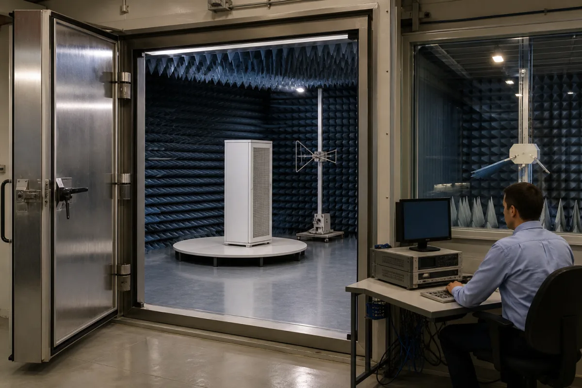
Industrial Electromagnetic Interference (EMI) Shielding Test Chamber System in a manufacturing environment
Representative product image. Confirm appearance and specifications with the manufacturer.

Product Specifications

Technical details and manufacturing context for Industrial Electromagnetic Interference (EMI) Shielding Test Chamber System

Definition
This industrial system is a complete, modular shielded chamber designed to create a controlled electromagnetic environment for Electromagnetic Interference (EMI) and Electromagnetic Compatibility (EMC) testing. It provides an isolated space to measure emissions from electrical devices and assess their immunity to external interference. The system is essential for compliance testing, product development, and quality assurance in the manufacture of electrical equipment, ensuring devices operate reliably without causing or succumbing to electromagnetic disturbances.

The chamber is constructed from modular conductive panels, typically galvanized steel, with copper alloy mesh and RF-shielding gaskets to ensure continuity. Ferrite tiles are used to absorb high-frequency energy. The system includes specialized doors and windows that maintain shielding integrity. Internal antennae, sensors, and signal generators are used to measure device emissions and apply controlled interference, while monitoring equipment records results within the isolated environment.

Key specifications include a shielding effectiveness of at least 100 dB over a frequency range of 10 kHz to 18 GHz, internal dimensions of 3000×3000×2500 mm (L×W×H), and a door aperture of 1800×2000 mm. The system supports a filtered power feed capacity of 3×400 kVA, with a power supply voltage of 380–415 V AC (three-phase, 50/60 Hz) and a maximum power consumption of 5 kW. The ambient noise floor is -90 dBm, and the operating temperature range is 15–35 °C with relative humidity 20–80% (non-condensing). The ingress protection rating is IP54, and the floor loading capacity is 1000 kg/m². The approximate weight is 4500 kg.

These values are reference ranges for directory purposes and must be confirmed with the legal manufacturer for the specific model and application. Standards such as IEC 61000-4-21, IEC 60068-2-1, IEC 60068-2-78, IEC 60529, and IEC 60038 are listed as verification references, not as proof of certification or compliance.
Working Principle
The system operates as a Faraday cage, using modular conductive panels and specialized doors/windows to attenuate external electromagnetic fields. Internal antennae, sensors, and signal generators are used to measure device emissions and apply controlled interference. Monitoring equipment records the results within the isolated environment. The shielding effectiveness is achieved through the use of galvanized steel panels, copper alloy mesh, RF-shielding gaskets, and ferrite tiles, which together provide attenuation of at least 100 dB across the specified frequency range.
Common Materials
Galvanized Steel, Copper Alloy Mesh, RF-shielding Gaskets, Ferrite Tiles
Technical Parameters
ParameterTypical rangeNotes & selection driver
Shielding EffectivenessRequired≥100 dBAttenuation of electromagnetic fields at specified frequencies (e.g., 30 MHz - 1 GHz)IEC 61000-4-21
Internal DimensionsRequired3000×3000×2500 m (LxWxH)Clear internal working space of the main chamber
Frequency RangeRequired10 kHz – 18 GHz HzOperational frequency range for specified shielding performance
Door ApertureRequired1800×2000 m (WxH)Size of the RF-shielded access door for equipment loading
Filtered Power Feed Capacity3×400 kVAMaximum filtered AC power capacity supplied into the chamber
Ambient Noise Floor-90 dBm dBμV/mMaximum residual electromagnetic field strength inside the empty, sealed chamber
Operating Temperature Range15–35 °CNon-condensingIEC 60068-2-1
Relative Humidity Range20–80 % RHNon-condensingIEC 60068-2-78
Ingress Protection RatingIP54Dust and splash proofIEC 60529
Weight4500 kgApproximate, depends on configuration
Floor Loading Capacity1000 kg/m²Reinforced floor available
Power Supply Voltage380–415 V ACThree-phase, 50/60 HzIEC 60038
Power Consumption5 kWPeak, with all systems active

Ranges are indicative industry figures for RFQ preparation, not a supplier commitment. Confirm every value and standard with the legal manufacturer before ordering.

Components / BOM
  • Modular Shielded Enclosure
    Primary structure providing electromagnetic isolation
    Material: Galvanized steel panels with welded seams
  • RF-shielded Access Door
    Provides personnel and equipment access while maintaining shielding integrity
    Material: Aluminum frame with beryllium copper finger stock gaskets
  • Power Line Filter Panel
    Filters electromagnetic noise from incoming AC power lines
    Material: Stainless steel housing, ferrite cores
  • Waveguide Ventilation Panel Optional
    Allows air flow for cooling while blocking RF signals above cutoff frequency
    Material: Aluminum honeycomb structure
  • Interface Panel Optional
    Provides filtered pass-throughs for data, signal, and control cables
    Material: Aluminum with coaxial bulkhead connectors
  • Internal Antenna Mounting System Optional
    Adjustable mast or turntable system for positioning measurement antennae
    Material: Non-conductive composite or treated wood
  • Ferrite Tiles Optional
    Line the walls to absorb low-frequency energy instead of reflecting it back into the chamber.
  • Measurement Antennae
    Pick up the emissions from the device under test and radiate the interference used in immunity tests.

Industry Taxonomies & Aliases

Commonly used trade names and technical identifiers for Industrial Electromagnetic Interference (EMI) Shielding Test Chamber System.

Industrial Ecosystem & Supply Chain Structure

Complementary Systems
Downstream Applications
Specialized Tooling

Application Fit & Sizing Matrix

Operational Limits
pressure: Atmospheric pressure operation only, no pressure differential capability
other spec: Shielding effectiveness: 80-120 dB (depending on frequency range), Frequency range: 10 kHz to 18 GHz, Test volume: Varies by model (typically 1-100 m³)
temperature: Typically 10°C to 40°C (operating environment), chamber internal temperature stable within ±2°C
Media Compatibility
✓ Electronic control units (ECUs) ✓ Telecommunications equipment ✓ Medical electronic devices
Unsuitable: High-voltage power transmission equipment (due to size constraints and potential for arcing)
Sizing Data Required
  • Maximum dimensions of equipment under test (EUT)
  • Required frequency range for testing
  • Required shielding effectiveness (dB) at target frequencies

Reliability & Engineering Risk Analysis

Failure Mode & Root Cause
Shield Degradation
Cause: Corrosion or physical damage to conductive gaskets, seams, or mesh due to environmental exposure, mechanical wear, or improper handling, compromising electromagnetic attenuation.
RF Leakage
Cause: Poor sealing at doors, vents, or cable penetrations from worn seals, misalignment, or inadequate maintenance, allowing electromagnetic signals to escape or enter.
Maintenance Indicators
  • Audible hum or buzzing from electrical components, indicating potential arcing or loose connections within shielding.
  • Visible corrosion, gaps, or deformation on door seals, vents, or panel joints, suggesting compromised EMI integrity.
Engineering Tips
  • Implement regular RF leakage testing with an antenna or field probe to detect and address weak points before significant degradation occurs.
  • Maintain controlled environment (e.g., humidity, temperature) and use non-corrosive cleaners on conductive surfaces to prevent shield deterioration.

Indicative industry ranges for design and RFQ preparation. Confirm the exact figures and applicable standard with the manufacturer before specifying.

Compliance & Manufacturing Standards

Applicable Standards
ISO 11452-2: Road vehicles - Component test methods for electrical disturbances from narrowband radiated electromagnetic energy - Part 2: Absorber-lined shielded enclosure ANSI C63.4: American National Standard for Methods of Measurement of Radio-Noise Emissions from Low-Voltage Electrical and Electronic Equipment in the Range of 9 kHz to 40 GHz DIN EN 50147-1: Anechoic chambers - Part 1: Shield attenuation measurement

Quoted from the published standard.

Manufacturing Precision
  • Shielding effectiveness: >=100 dB at 1 GHz
  • Door seal gap: <=0.5 mm continuous
Quality Inspection
  • Shielding effectiveness verification test (per MIL-STD-285 or IEEE 299)
  • Leak detection test using RF gasket compression measurement

Manufacturers of Industrial Electromagnetic Interference (EMI) Shielding Test Chamber System

Manufacturer profiles associated with Industrial Electromagnetic Interference (EMI) Shielding Test Chamber System.

Sourcing Industrial Electromagnetic Interference (EMI) Shielding Test Chamber System from China?
Tell us your specification and target quantity — we will match it against manufacturer records and come back with the factories that fit.
Request manufacturers We manufacture this

Manufacturer listings support early research and capability understanding. They are not certification, ranking, or transaction guarantees.

Share this page
Technical documentation
Request current drawings, revision history, and a signed specification sheet.
Manufacturing capability
Verify equipment lists, process limits, capacity, and representative production evidence.
Inspection readiness
Confirm test methods, calibrated equipment, sampling plans, and traceable reports.
Supplier transparency
Check the legal entity, factory address, ownership, certifications, and direct contacts.

CNFX does not score or rank suppliers. Buyers must verify all claims and documents with the legal manufacturer before ordering.

Frequently Asked Questions

What is the shielding effectiveness of this chamber?

The shielding effectiveness is at least 100 dB over the frequency range of 10 kHz to 18 GHz, as per the reference values. This should be verified with the manufacturer for the specific configuration.

What are the internal dimensions and door size?

The internal dimensions are 3000×3000×2500 mm (L×W×H), and the door aperture is 1800×2000 mm. These are reference values and may vary based on the model.

What power supply is required?

The system requires a three-phase power supply of 380–415 V AC, 50/60 Hz, with a filtered power feed capacity of 3×400 kVA. Maximum power consumption is 5 kW.

What environmental conditions are supported?

The operating temperature range is 15–35 °C, and relative humidity is 20–80% (non-condensing). The ingress protection rating is IP54, and the floor loading capacity is 1000 kg/m².

Data Basis

Editorial classification, named public sources where available, and source-reviewed manufacturer records.

Preliminary Technical Classification
This page supports structured research, RFQ preparation, and supplier evaluation. It does not replace buyer-led supplier qualification, standards review, or technical approval.
Buyer enquiry

Request manufacturing insight for Industrial Electromagnetic Interference (EMI) Shielding Test Chamber System

Ask for use case, specification boundaries, supplier type, and RFQ preparation information for this product.

Where it goes
Straight to the CNFX editorial desk, and to the manufacturer if this product is linked to a claimed profile. Nothing is broadcast to a supplier list.
Your details stay here
We do not sell or rent enquiry data, and we do not add you to a mailing list. Used only to answer this request.
No commission, no middleman
CNFX is a directory. We take no cut of any order and never negotiate on a supplier's behalf.
What we don't claim
A listing is not an endorsement. Qualify every supplier and verify every figure yourself before ordering.

Your business information is used only to process this request.

Thank you! Your message has been sent. We'll respond within 1–3 business days.
Sorry, we couldn't send your message. Please try again, or email us at [email protected].

Need to Manufacture Industrial Electromagnetic Interference (EMI) Shielding Test Chamber System?

Compare manufacturer profiles with relevant product and process capability.

Previous Product
Industrial Electromagnetic Flow Meter Calibrator
Next Product
Industrial Electromagnetic Relay Coil Assembly
Get QuotesChat