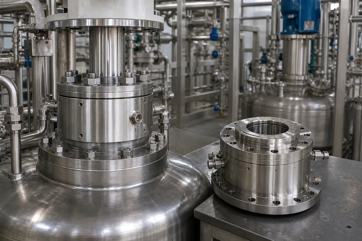
Chemical reactor sealing gland: packed stuffing box for top-entry agitator shafts
Packed agitator shaft seal · flanged stuffing box, braided packing rings, lantern ring and split gland follower on a reactor nozzle
On a stirred vessel with a packed seal, the agitator shaft leaves the vessel through a flanged housing filled with rings of braided packing. A split gland follower, pulled down by studs and nuts, squeezes the rings against the shaft and the housing bore; a lantern ring in the middle of the set can carry grease or flush to the packing. It leaks a little by design, is adjusted from outside, and is serviced without lifting the drive. The questions are how many rings and at what pressure and temperature the box is rated, how well the housing is aligned with the shaft, and how the gland is run in.
Compression-packing stuffing boxes (sealing glands) for top-entry agitator and mixer shafts on reactors and process tanks: the flanged gland housing, braided packing rings, lantern ring and lubrication fitting, split gland follower, studs and adjusting nuts, and their fitting and run-in. Single, dual and cartridge mechanical seals, including mechanical seals for mixers and agitators, are covered on the Mechanical seal page; the reactor vessel, jacket and drive on the Chemical reactor (jacketed stirred tank) page; and the impellers on the Chemical reactor agitator blade page.
CNFX editorial research · Sources checked October 12, 2026 · 5 sources
Four rings or six rings with a lantern ring: what sits inside an agitator stuffing box
Chemineer's installation manuals for its QED Plus and 50DTA agitators describe two packed arrangements. The 50DTA stuffing box holds four rings of self-lubricated packing and needs no added lubrication for the life of the packing. [2] The QED auxiliary stuffing box, bolted to the vessel nozzle with a gasket supplied by others, takes three rings of packing, a lantern ring, further packing rings and a gland plate with a split gland; the six-ring box is supplied with six rings and a lantern ring. [1]
When the rings are installed, RS Components' packing leaflet asks for each ring to be tapped home separately with the joints of successive rings staggered, preferably at 90°, and Chemineer likewise asks for the packing split to be staggered and each ring seated as it is installed. [5][1] Freudenberg's datasheets add that the cut ends should be distributed symmetrically around the circumference and the cap nuts tightened evenly. [3]
Part
What it does
Published detail
Stuffing box flange (gland housing)
Bolts to the vessel nozzle and holds the packing around the shaft.
Gasket and flange bolts supplied by others on the QED auxiliary box [1]
Packing rings
Compressed axially by the gland follower so they press on shaft and bore.
Merkel describes its Flexalon 6250 braid as square-section, sealing by axial compression with a gland follower [3]
Lantern ring
Spacer in the packing set that brings grease or flush to the rings.
Three rings below it on the QED auxiliary box [1]; channel to be in line with the lubricant feed and allow for movement during take-up [5]
Grease fitting and pipe plug
Feed lubricant to the lantern ring.
Pump grease until it comes out of the plug hole; re-lubricate about every 24 hours where the packing is not self-lubricating [1]
Split gland and gland plate, studs, adjusting nuts
Apply and adjust the packing load; split so it can be removed around the shaft.
Gland must sit square with the packing housing [1][2]
Ask for the drawing of the gland housing with ring count and cross-section, lantern ring position, lubrication connection, and whether the gland follower is split.
02
Ratings: 50 psig and 100 psig agitator boxes against the pressure and speed guidelines of packing yarns
An agitator maker rates the assembled box; a packing maker gives guideline values for the braid alone. The two sets of numbers are far apart and are not interchangeable.
Editorial calculation: 50 psig is about 3.4 bar and 100 psig about 6.9 bar, while 2.5 MPa is 25 bar, so the yarn guideline is about 3.6 times the 6.9 bar rating of the QED-A box and about 7 times the 3.4 bar rating of the 50DTA box. Freudenberg states its values come from a limited number of laboratory tests and are non-binding guidelines whose suitability depends on the actual operating conditions. [3][4] Chemineer tells operators not to run shaft seals at temperatures or pressures higher than those the unit was designed for. [1] Use the rating of the assembled box, not the yarn.
Editorial calculation, with an assumed 80 mm agitator shaft at 125 rpm: surface speed = π × 0.08 m × 125 / 60 ≈ 0.52 m/s, about one fortieth of the 20 m/s guideline for the Kombilon braid. [4] On slow agitators the pressure, temperature and shaft movement decide the packing, not the speed. Freudenberg lists low leakage rates even with slight shaft deflection among the advantages of the Kombilon 6742 braid. [4]
Item
Pressure
Temperature
Speed
Chemineer 50DTA stuffing box, four rings self-lubricated packing
State vessel design pressure and vacuum, the vapour or liquid at the seal, temperature at the nozzle, shaft diameter and speed, and whether the packing may be wetted by product or must be self-lubricating.
03
Housing bore, shaft finish and alignment the gland needs
Packing does not tolerate a shaft that wanders in the bore. RS Components' leaflet says the stuffing box must not be used as a guide bearing and that bearings should be provided as close to the box as possible. [5]
RS Components also recommends square faces at the base of the box and on the leading edge of the follower, because bevelled faces force packing onto the shaft at each end and promote extrusion through the clearances. [5] The leaflet's 0.1 mm runout limit is general guidance for pumps and valves; Chemineer's 0.127 mm figure is an alignment setting for the housing during agitator installation. Check both against the drawing for a long overhung agitator shaft. [5][1]
Running in the packing: one flat on the gland nuts every 15 minutes, and when to repack
Both Chemineer manuals give the same start-up routine: tighten the gland nuts finger tight, start the agitator, then take up the nuts gradually, one flat at a time, allowing 15 minutes between each take-up for the packing to reseat itself, until the leakage is acceptable. [1][2]
For the QED-A box, Chemineer asks for the packing to sit for five or ten minutes after the first tightening so that it can cold flow and adjust to gland pressure, then for the nuts to be loosened back to finger tight before start-up. Once run in, the gland nuts on the auxiliary box are retightened on a schedule that can vary from weekly to monthly depending on the sealing wanted, and over-tightening wears packing prematurely and scores the shaft. [1]
RS Components says the follower should be long enough to enter to 40% of the available packing space and that the packing should be replaced once that much take-up has occurred. [5] Editorial calculation, with an assumed six rings of 10 mm section: the packing space is 60 mm deep, so repacking is due after about 24 mm of follower travel. Its failure table links no leakage at start-up to an over-tightened gland, and a charred or blackened bore of used packing to lubrication failure. [5]
Ask the supplier for the run-in procedure, maximum gland take-up and replacement packing specification with the box.
05
Data to send for a reactor agitator stuffing box
Paste it into your enquiry below or into an email to a maker, then replace every bracket.
Vessel: [design pressure and vacuum; temperature at nozzle; vapour or liquid at seal]
Shaft: [diameter; speed; overhang; steady bearing; runout]
Nozzle: [flange standard and size; bolt circle; gasket]
Packing: [ring count and section; yarn; self-lubricating or greased]
Lantern ring: [yes/no; grease or flush connection]
Gland: [split follower; studs and nuts; material]
Documents: [drawing; rating of assembled box; run-in procedure]
Explore company information and manufacturing capabilities, then discuss the scope of your project with a relevant supplier.
Share this page
Compiled and source-reviewed by the CNFX editorial team.
Each manufacturer above links to the page on that company's own website where the product is listed, with the date we checked it. How we source and review
· Page last updated 13 October 2026
Buyer questions
What pressure can a packed agitator stuffing box take?
It is set by the assembled box. Chemineer rates its 50DTA four-ring box at 50 psig at 400 °F and its QED-A six-ring box at 100 psig at 300 °F. [2][1]
What is the lantern ring for?
It sits within the packing set and lines up with a lubricant feed; Chemineer's six-ring auxiliary box has three rings below the lantern ring and a grease fitting. [1][5]
How is new agitator packing tightened?
Finger tight at start, then one flat on the gland nuts at a time with 15 minutes between take-ups until leakage is acceptable. [1][2]
Sources and what still needs a direct check
Sources checked 2026-10-12. Chemineer (NOV) installation manuals describe stuffing boxes on its own agitators; Freudenberg FST datasheets give guideline values for its packing braids; RS Components' leaflet covers gland design and packing fitting.