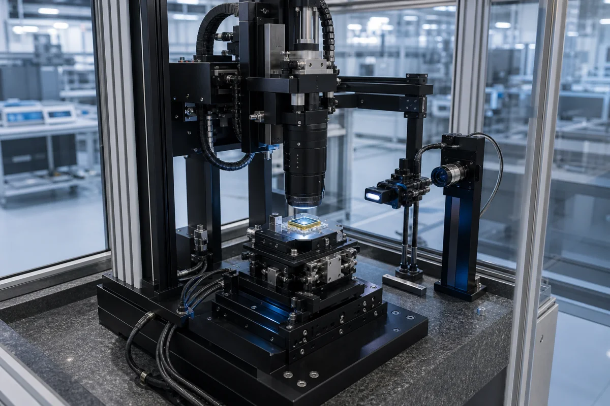
Active optical alignment station (camera module active alignment)
Camera module active alignment (AA) equipment · Six-axis lens-to-sensor positioning on a powered sensor, through-focus SFR scoring at centre and corners, hexapod travel, repeatability and stiffness, adhesive dispense and UV cure, cure-shrinkage offset, and the tilt error budget
An active optical alignment station is the machine in a camera module line that holds the lens over a powered, streaming image sensor, moves it in up to six axes while software scores the live image of a target, and locks the best position by curing adhesive — so each lens is aligned to its own sensor rather than relying on stacked mechanical tolerances. Ask three things first: what focus budget the module design leaves (pixel size, f-number, field and tilt tolerance), which axes, travel and repeatability the motion system must have to meet it, and which adhesive, cure and verification steps the line will run.
Active alignment (AA) equipment for assembling lenses to image sensors in camera modules: the multi-axis positioner (hexapod or stacked stages), lens gripper and sensor fixture, target and illumination, image-quality measurement software, adhesive dispensing and UV cure, and the lens loading, clamping and centring fixtures that feed it. Lens centring and edging machines, stand-alone MTF test benches, fibre and photonics alignment and passive (mechanical) camera assembly are outside this page except where compared.
CNFX editorial research · Sources checked October 11, 2026 · 4 sources
Set the alignment method and the focus budget it must meet
Commonlands, a camera lens maker, describes active alignment as positioning the lens relative to the powered image sensor in up to six degrees of freedom while scoring through-focus sharpness on live video — a system SFR measurement of the assembled lens and sensor, not the lens MTF on a data sheet — and then locking the position with UV-cure adhesive. Because the sensor is streaming, each lens is aligned to the true position of its own die, absorbing placement and stack-up tolerances; the company notes that errors inside the lens or sensor package, die warp, field curvature and adhesive shrinkage are not removed by the rigid-body move. [1]
It sets out the six axes as X, Y and Z translation (Z sets focus, X and Y decentre) and tip, tilt and rotation (tip and tilt set the corner focus gradient, rotation sets geometric registration), and contrasts a threaded M12 lens, which controls only Z. Its worked example: on a 1/2.3-inch sensor with a corner image height of about 3.95 mm, a working f-number of 2.0 and an allowed blur of 3 µm give a depth-of-focus budget of ±6 µm, and a tilt of 1.5 mrad (about 0.09°) alone moves one corner to +6 µm and the opposite corner to −6 µm, leaving nothing for Z or field curvature. [1]
A patent application assigned to Semiconductor Components Industries (onsemi) describes the conventional AA loop: a calibration target is viewed through the camera optics, contrast-detection algorithms measure edge contrast, and a multi-axis manipulator moves the lens to maximise it; it proposes using phase-detection pixels in the sensor to tell the alignment system how far and in which direction to move, with computer-controlled positioners able to move the lens in one to six axes, and the alignment locked by curing UV adhesive that stays uncured during alignment. [2]
Give the supplier the module drawing (lens barrel, holder, sensor package and board), sensor interface and resolution, pixel size, working f-number, field of view and object distance, the target and image-quality metric (SFR, MTF, contrast), centre and corner limits, the axes that must be adjusted, required cycle time and yield, and whether fixed-focus or autofocus modules are built.
02
Set the positioner, adhesive dispense and cure
Physik Instrumente (PI) describes hexapods for six-axis active optical alignment as a single platform on six motorised struts, equivalent to an XYZ stack with a rotation stage and two-axis goniometer, whose pivot point can be placed anywhere in space — such as at an optical focus — and whose controller adds a waveform generator, data recorder and gradient-search alignment routines; it says multiple hexapods carrying lens elements can optimise MTF simultaneously, and that optimisation can continue during adhesive curing to correct curing stresses. [3]
Its H-811.S2 miniature hexapod data lists travel of ±17 mm in X, ±16 mm in Y and ±6.5 mm in Z, rotation of ±10°, ±10° and ±21°, maximum velocity 25 mm/s (10 mm/s recommended), minimum incremental motion of 1 µm in X and Y and 0.5 µm in Z, unidirectional repeatability of ±0.5 µm in X and Y, ±0.2 µm in Z and ±6 µrad in tip and tilt, stiffness 0.7 N/µm in X and Y and 8 N/µm in Z, a load of 2.5 kg with the base horizontal (0.9 kg in any orientation) and an operating range of 0 to 50 °C. [4]
Commonlands lists the AA cycle as: dispense adhesive beads on the holder or barrel (the glue gap must absorb the whole Z range being corrected); grip and coarse-position the lens while the sensor streams video; sweep through Z scoring SFR at the centre and four corner regions; move tip, tilt, X, Y and Z until centre and corner scores peak inside one shared window; then cure with UV LEDs within seconds while the gripper holds the pose, with the target pre-offset by the characterised cure shrinkage, followed by thermal post-cure where the chemistry needs it and an end-of-line through-focus check. It notes UV acrylates cure fastest, modified epoxies, "often dual-cure UV plus thermal, are more stable", all adhesives shrink, and a single fibre under the bond line becomes a permanent tilt. [1]
Editorial calculation: against the ±6 µm example budget above, a tip-tilt repeatability of ±6 µrad moves a 3.95 mm corner by about 3.95 mm × 6 µrad ≈ 0.024 µm, roughly 0.4% of the 1.5 mrad tilt that would consume the whole budget; in this example the positioner's repeatability is not the limiting term, so ask the supplier for measured post-cure shift and end-of-line yield. [1][4]
03
No station maker linked yet: what to ask for
No active alignment station maker is linked to this page yet. When you request quotations, ask each for positioner data in the form PI publishes for the H-811.S2 and for measured post-cure shift on a module like yours.
04
Positioner, gripper and fixture, target, scoring software, dispenser, UV head and controller
The rows follow the AA cycle described above, from holding the lens to curing the bond.
Travel, repeatability, speed, load and cure for the quotation
The focus budget and cycle time come from your module and line. The middle column uses PI H-811.S2 data and the Commonlands worked example; achieved post-cure accuracy must come from the supplier.
Explore company information and manufacturing capabilities, then discuss the scope of your project with a relevant supplier.
Share this page
Compiled and source-reviewed by the CNFX editorial team.
Each manufacturer above links to the page on that company's own website where the product is listed, with the date we checked it. How we source and review
· Page last updated 13 October 2026
Buyer questions
Why use active alignment instead of a threaded lens?
A threaded lens controls only focus; active alignment also corrects decentre, tip and tilt against the live image, which matters when the corner focus budget is small. [1]
How does the station know where the best position is?
It scores a target imaged through the lens by the module's own sensor, by SFR or edge contrast, and some methods use phase-detection pixels to calculate the move. [1][2]
Why can the lens move after alignment?
Adhesive shrinks during cure, so production measures the post-cure shift and offsets the target; optimisation can also continue during curing. [1][3]
Sources and what still needs a direct check
Sources checked 2026-10-11. The Commonlands guide is a lens maker's account of the process, the onsemi document a patent application, and the PI pages one positioner maker's description and data; accuracy, cycle time and yield for your module must come from the supplier offered.