Editorial Technical Reference

Active Feedback Sensor

This page explains how Active Feedback Sensor is classified within Computer, Electronic and Optical Product Manufacturing. Technical values and manufacturer relationships are research references; confirm the current specification and supplier evidence for each order.

Technical Definition & Core Assembly

A sensor that provides real-time feedback on alignment status in optical systems.
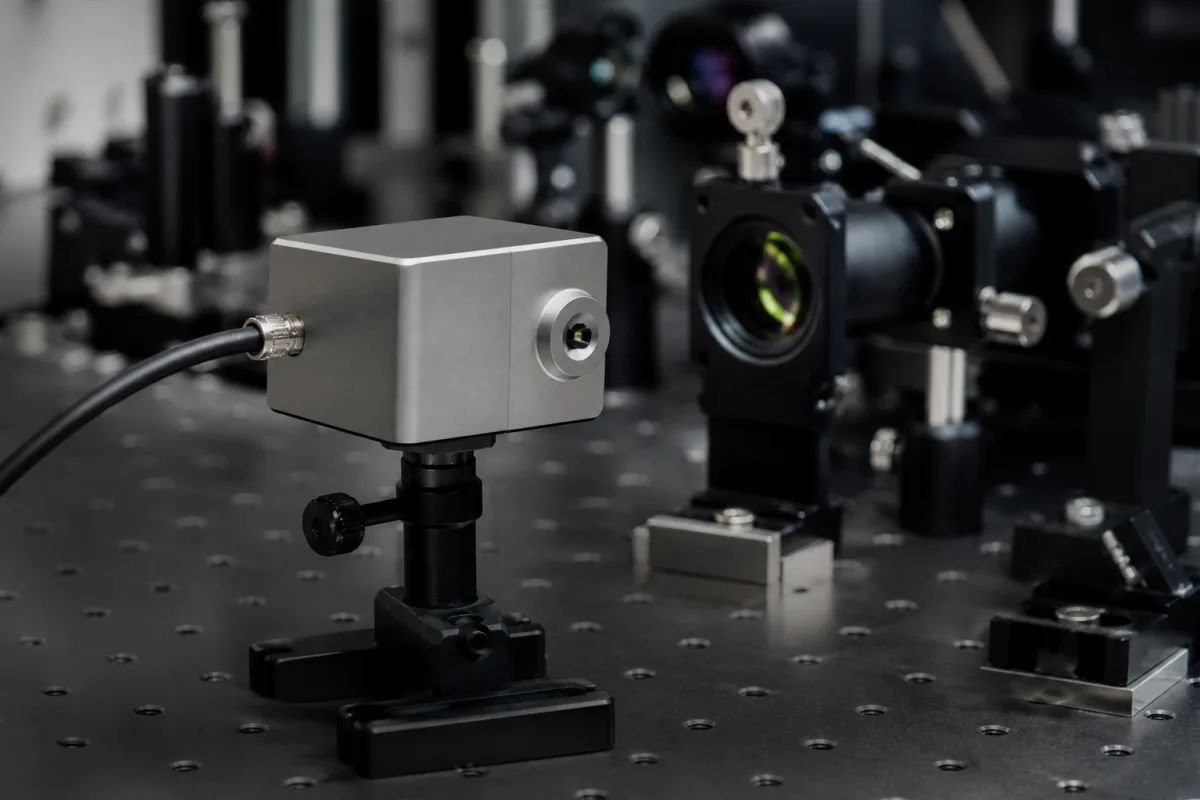
Active Feedback Sensor in a manufacturing environment
Representative product image. Confirm appearance and specifications with the manufacturer.

Product Specifications

Technical details and manufacturing context for Active Feedback Sensor

Definition
The Active Feedback Sensor is a component used in optical alignment systems, such as the Active Optical Alignment Station. It continuously monitors optical alignment parameters and provides real-time feedback signals to the control system, enabling dynamic adjustment and optimization of optical components during manufacturing or calibration processes. The sensor operates on optical detection methods, including laser interferometry, CCD imaging, or photodiode arrays, to measure alignment parameters. These measurements are converted into electrical signals and transmitted to the control system for processing and generating adjustment commands. The sensor is designed for integration into automated alignment equipment, where it supports closed-loop control to maintain precise alignment. Key specifications include a detection range of 0.1–5 m, accuracy of ±0.01 mm, response time of ≤10 ms, and an analog output signal of 4–20 mA. It operates on a 24 V DC supply (±10%) and within a temperature range of -40 to 85 °C. The housing is made of corrosion-resistant stainless steel (316L) and offers ingress protection ratings from IP54 to IP65, depending on the model. The sensor weighs ≤200 g and has compact dimensions of 30×30×15 mm. These parameters are reference values and must be verified with the manufacturer for the specific model and application. The sensor is suitable for use in cleanroom and industrial environments, but proper installation and calibration are essential for optimal performance. Regular maintenance and verification of alignment accuracy are recommended to ensure reliable operation. The sensor is not a standalone measurement device; it requires integration with a control system and appropriate software for data processing. Users should consult the manufacturer's documentation for detailed installation, operation, and maintenance procedures.
Working Principle
The Active Feedback Sensor uses optical detection methods such as laser interferometry, CCD imaging, or photodiode arrays to measure alignment parameters. It converts these optical measurements into electrical signals, typically a 4–20 mA analog output, which are transmitted to the control system. The control system processes these signals and generates adjustment commands to correct any misalignment in real time. The sensor's response time of ≤10 ms enables rapid feedback for dynamic control. The detection range of 0.1–5 m allows for flexible placement within the optical system. The sensor's accuracy of ±0.01 mm ensures precise alignment feedback. The sensor is powered by a 24 V DC supply and operates within a temperature range of -40 to 85 °C. Its housing is made of stainless steel 316L, providing corrosion resistance and durability. The ingress protection rating of IP54–IP65 ensures dust and water resistance, making it suitable for various industrial environments.
Common Materials
Silicon photodiodes, Optical glass, Aluminum housing
Technical Parameters
ParameterTypical rangeNotes & selection driver
Detection Range0.1–5 mRange for alignment feedback
Accuracy±0.01 mmTypical accuracy for alignment
Response Time≤10 msFast feedback for real-time control
Output Signal4–20 mAAnalog output proportional to alignment
Supply Voltage24 ±10% V DCStandard industrial supply
Operating Temperature-40–85 °CExtended temperature range
Ingress ProtectionIP54–IP65Dust and water resistanceIEC 60529
Housing Material316LCorrosion-resistant stainless steelASTM A240
Weight≤200 gLightweight for easy integration
Dimensions30×30×15 mmCompact footprint

Ranges are indicative industry figures for RFQ preparation, not a supplier commitment. Confirm every value and standard with the legal manufacturer before ordering.

Components / BOM

Application & selection

Application Fit & Sizing Matrix

Operational Limits
pressure: 0 to 100 psi
other spec: Alignment accuracy: ±0.1 arcsec, Response time: <10 ms
temperature: -20°C to +85°C
Media Compatibility
✓ Clean air environments ✓ Optical glass surfaces ✓ Vacuum chambers
Unsuitable: High-vibration industrial machinery
Sizing Data Required
  • Optical system wavelength range
  • Required alignment precision
  • Mounting interface dimensions

Risk, maintenance & compliance

Reliability & Engineering Risk Analysis

Failure Mode & Root Cause
Signal Drift/Inaccuracy
Cause: Sensor element degradation due to thermal cycling, contamination ingress, or electronic component aging, leading to calibration loss and unreliable feedback.
Complete Signal Loss
Cause: Wiring/connection failure from vibration-induced fatigue, corrosion at terminals, or internal circuit board damage from electrical transients or moisture ingress.
Maintenance Indicators
  • Erratic or fluctuating output readings inconsistent with process conditions
  • Audible electrical arcing/humming or visible sparking/discoloration at sensor housing/connections
Engineering Tips
  • Implement regular calibration checks using traceable standards and environmental compensation to maintain signal integrity across operating conditions.
  • Use vibration-resistant mounting, sealed connectors, and surge protection devices to prevent mechanical/electrical damage and ensure stable operation.

Indicative industry ranges for design and RFQ preparation. Confirm the exact figures and applicable standard with the manufacturer before specifying.

Compliance & Manufacturing Standards

Applicable Standards
IEC 61000-6-2 Electromagnetic Compatibility (EMC) CE Marking (EU Machinery Directive 2006/42/EC)

Quoted from the published standard.

Manufacturing Precision
  • Output Signal Accuracy: +/-0.5% of full scale
  • Response Time: +/-10 milliseconds
Quality Inspection
  • Environmental Stress Testing (Temperature/Humidity/Vibration)
  • Calibration Verification Against Traceable Standards
Technical documentation
Request current drawings, revision history, and a signed specification sheet.
Manufacturing capability
Verify equipment lists, process limits, capacity, and representative production evidence.
Inspection readiness
Confirm test methods, calibrated equipment, sampling plans, and traceable reports.
Supplier transparency
Check the legal entity, factory address, ownership, certifications, and direct contacts.

Compare the published product scope and source details, then include your specifications and quantity in an enquiry.

Manufacturers of Active Feedback Sensor

Manufacturer profiles associated with Active Feedback Sensor.

Sourcing Active Feedback Sensor from China?
Tell us your specification and target quantity — we will match it against manufacturer records and come back with the factories that fit.
Request manufacturers We manufacture this

Explore company information and manufacturing capabilities, then discuss the scope of your project with a relevant supplier.

Buyer enquiry

Request manufacturing insight for Active Feedback Sensor

Ask for use case, specification boundaries, supplier type, and RFQ preparation information for this product.

Where it goes
Straight to the CNFX editorial desk, and to the manufacturer if this product is linked to a claimed profile. Nothing is broadcast to a supplier list.
Your details stay here
We do not sell or rent enquiry data, and we do not add you to a mailing list. Used only to answer this request.
No commission, no middleman
CNFX is a directory. We take no cut of any order and never negotiate on a supplier's behalf.
What to include
Share your product specifications, quantity, destination and target delivery date.

Your business information is used only to process this request.

Thank you! Your message has been sent. We'll respond within 1–3 business days.
Sorry, we couldn't send your message. Please try again, or email us at [email protected].

Frequently Asked Questions

What is the detection range of the Active Feedback Sensor?

The detection range is 0.1 to 5 meters, as listed in the reference specifications. However, the actual range may vary depending on the specific model and application. Always verify with the manufacturer for your particular setup.

What output signal does the sensor provide?

The sensor provides an analog output signal of 4–20 mA, which is proportional to the alignment status. This signal is typically connected to a control system for processing and adjustment.

What is the operating temperature range?

The sensor is designed to operate within a temperature range of -40 to 85 °C. Ensure that the installation environment stays within these limits to maintain performance.

Is the sensor suitable for outdoor or dusty environments?

The sensor has an ingress protection rating of IP54 to IP65, indicating dust and water resistance. However, the exact rating depends on the model. Check the manufacturer's specifications for the specific model to confirm suitability for your environment.

Related equipment

Applied To / Applications

This component is essential for the following industrial systems and equipment:

Data Basis

Editorial classification, named public sources where available, and source-reviewed manufacturer records.

Preliminary Technical Classification
This page supports structured research, RFQ preparation, and supplier evaluation. It does not replace buyer-led supplier qualification, standards review, or technical approval.

Need to Manufacture Active Feedback Sensor?

Compare manufacturer profiles with relevant product and process capability.

Previous Product
XY Positioning Stage
Last Product
Get QuotesChat