Editorial Technical Reference

Analog Front-End (AFE)

This page explains how Analog Front-End (AFE) is classified within Computer, Electronic and Optical Product Manufacturing. Technical values and manufacturer relationships are research references; confirm the current specification and supplier evidence for each order.

Technical Definition & Core Assembly

An Analog Front-End (AFE) is a critical component of an Application-Specific Integrated Circuit (ASIC) responsible for interfacing with the physical world.
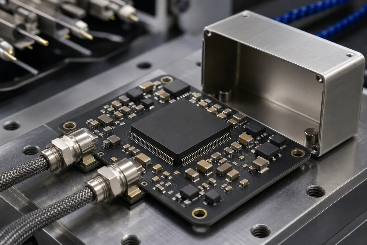
Analog Front-End (AFE) in a manufacturing environment
Representative product image. Confirm appearance and specifications with the manufacturer.

Product Specifications

Technical details and manufacturing context for Analog Front-End (AFE)

Definition
An Analog Front-End (AFE) is a critical component of an Application-Specific Integrated Circuit (ASIC) responsible for interfacing with the physical world. It conditions, amplifies, filters, and digitizes analog signals from sensors or transducers before passing them to the digital processing core of the ASIC for computation and control. The AFE operates at the boundary between the analog sensor domain and the digital processing domain, managing noise, impedance matching, and signal integrity. It typically includes operational amplifiers for signal conditioning, analog-to-digital converters (ADCs) to transform conditioned signals into digital bitstreams, and sometimes digital-to-analog converters (DACs) for control outputs. The AFE is fabricated on a silicon semiconductor substrate. Key parameters include supply voltage (3.3–5 V), power consumption (10–50 mW), input voltage range (0–Vref), resolution (12–24 bit), sampling rate (1–100 kSPS), signal-to-noise ratio (80–110 dB), total harmonic distortion (-80 to -100 dB), input impedance (1–10 MΩ), operating temperature range (-40 to 85 °C), and package type (QFN-32, footprint 5×5 mm). These values are directory reference ranges and must be confirmed for the specific model and application. The AFE is used in industrial, medical, and automotive applications where precise analog signal acquisition is required. When selecting an AFE, consider the sensor output characteristics, required resolution and sampling rate, power constraints, and environmental conditions. Verify model-specific parameters and standards with the legal manufacturer or supplier.
Working Principle
The AFE receives low-level analog signals from sensors. It uses operational amplifiers for signal conditioning, including amplification and filtering, to prepare the signal for conversion. An analog-to-digital converter (ADC) then digitizes the conditioned signal, producing a digital bitstream for the ASIC's digital core. Some AFEs also include digital-to-analog converters (DACs) for control outputs. The AFE manages noise, impedance matching, and signal integrity at the boundary between the analog sensor domain and the digital processing domain. It operates within specified supply voltage and temperature ranges, and its performance is characterized by parameters such as resolution, sampling rate, signal-to-noise ratio, and total harmonic distortion.
Common Materials
Silicon (Semiconductor Substrate)
Technical Parameters
ParameterTypical rangeNotes & selection driver
Supply Voltage3.3–5 VOperating range for analog and digital rails
Power Consumption10–50 mWAt full signal bandwidth
Input Voltage Range0–Vref VVref is the internal reference voltage
Resolution12–24 bitADC resolution
Sampling Rate1–100 kSPSMaximum sampling rate per channel
Signal-to-Noise Ratio80–110 dBAt maximum resolution
Total Harmonic Distortion-80–-100 dBAt full-scale input
Input Impedance1–10 MΩDifferential input impedance
Operating Temperature Range-40–85 °CIndustrial grade
Package TypeQFN-32Common package for AFE
Footprint5×5 mmQFN-32 package size

Ranges are indicative industry figures for RFQ preparation, not a supplier commitment. Confirm every value and standard with the legal manufacturer before ordering.

Components / BOM
  • Programmable Gain Amplifier (PGA)
    Amplifies weak analog sensor signals to optimal levels for the ADC, often with adjustable gain settings.
    Material: Semiconductor (Silicon)
  • Analog-to-Digital Converter (ADC)
    Converts the conditioned analog voltage signal into a corresponding digital bitstream for the ASIC's digital core.
    Material: Semiconductor (Silicon)
  • Anti-Aliasing Filter Part
    A low-pass filter that removes high-frequency noise and signals above the Nyquist frequency to prevent aliasing in the digitized signal.
    Material: Semiconductor (Silicon) / Passive Components (on-chip)
  • Multiplexer (MUX) Part
    Allows a single AFE channel to sequentially sample multiple analog input sources.
    Material: Semiconductor (Silicon)
  • Voltage Reference Part
    Provides a stable and precise reference voltage for the ADC and other analog circuits to ensure accurate conversion.
    Material: Semiconductor (Silicon)
  • Digital-to-Analog Converter Optional
    Turns digital control words back into analogue outputs, on AFEs that drive as well as sense.

Application & selection

Application Fit & Sizing Matrix

Operational Limits
temperature: -40°C to +125°C (typical industrial range)
voltage range: 1.8V to 5.5V supply (typical)
input impedance: >1MΩ (typical for high-impedance sensors)
signal bandwidth: DC to 10MHz (application dependent)
common mode rejection: >80dB (typical for noise rejection)
Media Compatibility
✓ Industrial sensor interfaces (pressure, temperature, flow) ✓ Biomedical instrumentation (ECG, EEG, EMG) ✓ Audio processing systems (microphone preamps, ADCs)
Unsuitable: High-voltage power line monitoring (>100V direct connection)
Sizing Data Required
  • Input signal amplitude range (mV to V)
  • Required resolution and sampling rate (bits, kSPS)
  • Power supply constraints and noise requirements

Risk, maintenance & compliance

Reliability & Engineering Risk Analysis

Failure Mode & Root Cause
Signal drift or offset
Cause: Thermal stress on components (e.g., resistors, op-amps) causing parameter shifts, or aging of electrolytic capacitors leading to leakage current changes.
Noise amplification or signal distortion
Cause: Degradation of filtering components (capacitors, inductors) due to environmental factors (moisture, temperature), or PCB contamination causing parasitic coupling.
Maintenance Indicators
  • Unexplained fluctuations or drift in processed signal readings beyond specified tolerances
  • Increased background noise or intermittent signal dropouts in the output, audible as crackling in audio applications or visible as spikes in data logs
Engineering Tips
  • Implement regular calibration and thermal cycling tests to detect early component drift, and use conformal coating on PCBs to protect against moisture and contaminants.
  • Design with derated, high-reliability components (e.g., low-ESR capacitors, precision resistors) and ensure proper EMI shielding and grounding to reduce environmental stress.

Indicative industry ranges for design and RFQ preparation. Confirm the exact figures and applicable standard with the manufacturer before specifying.

Compliance & Manufacturing Standards

Applicable Standards
IEC 61000-4-2 (Electrostatic Discharge Immunity) IEC 61000-4-4 (Electrical Fast Transient/Burst Immunity)

Quoted from the published standard.

Manufacturing Precision
  • Gain Accuracy: +/-0.1%
  • Offset Voltage: +/-0.5mV
Quality Inspection
  • Signal-to-Noise Ratio (SNR) Test
  • Total Harmonic Distortion (THD) Test
Technical documentation
Request current drawings, revision history, and a signed specification sheet.
Manufacturing capability
Verify equipment lists, process limits, capacity, and representative production evidence.
Inspection readiness
Confirm test methods, calibrated equipment, sampling plans, and traceable reports.
Supplier transparency
Check the legal entity, factory address, ownership, certifications, and direct contacts.

CNFX does not score or rank suppliers. Buyers must verify all claims and documents with the legal manufacturer before ordering.

Manufacturers of Analog Front-End (AFE)

Manufacturer profiles associated with Analog Front-End (AFE).

Sourcing Analog Front-End (AFE) from China?
Tell us your specification and target quantity — we will match it against manufacturer records and come back with the factories that fit.
Request manufacturers We manufacture this

Manufacturer listings support early research and capability understanding. They are not certification, ranking, or transaction guarantees.

Buyer enquiry

Request manufacturing insight for Analog Front-End (AFE)

Ask for use case, specification boundaries, supplier type, and RFQ preparation information for this product.

Where it goes
Straight to the CNFX editorial desk, and to the manufacturer if this product is linked to a claimed profile. Nothing is broadcast to a supplier list.
Your details stay here
We do not sell or rent enquiry data, and we do not add you to a mailing list. Used only to answer this request.
No commission, no middleman
CNFX is a directory. We take no cut of any order and never negotiate on a supplier's behalf.
What we don't claim
A listing is not an endorsement. Qualify every supplier and verify every figure yourself before ordering.

Your business information is used only to process this request.

Thank you! Your message has been sent. We'll respond within 1–3 business days.
Sorry, we couldn't send your message. Please try again, or email us at [email protected].

Frequently Asked Questions

What is the role of an AFE in an ASIC?

The AFE interfaces with analog sensors, conditioning and digitizing signals before they are processed by the digital core of the ASIC. It ensures signal integrity and accuracy.

What are typical supply voltage and power consumption ranges?

Typical supply voltage is 3.3–5 V, and power consumption ranges from 10–50 mW at full signal bandwidth. These are reference ranges; confirm for the specific model.

What resolution and sampling rate can an AFE provide?

Resolution ranges from 12 to 24 bits, and sampling rate from 1 to 100 kSPS per channel. Actual values depend on the specific AFE configuration.

How should I verify AFE specifications for my application?

Always check the datasheet and confirm parameters such as input voltage range, SNR, THD, and operating temperature with the legal manufacturer or supplier, as directory values are general references.

Related equipment

Applied To / Applications

This component is essential for the following industrial systems and equipment:

Data Basis

Editorial classification, named public sources where available, and source-reviewed manufacturer records.

Preliminary Technical Classification
This page supports structured research, RFQ preparation, and supplier evaluation. It does not replace buyer-led supplier qualification, standards review, or technical approval.

Need to Manufacture Analog Front-End (AFE)?

Compare manufacturer profiles with relevant product and process capability.

Previous Product
XY Positioning Stage
Last Product
Get QuotesChat