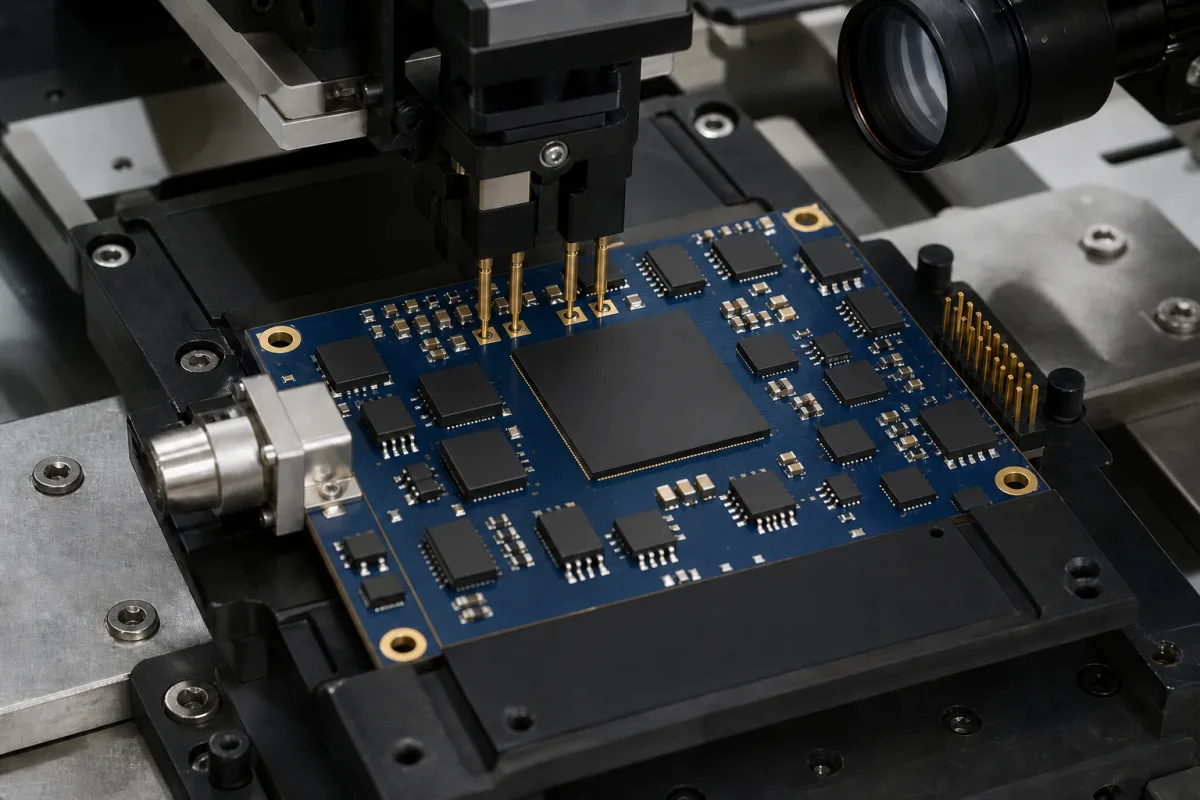
ADC evaluation board and data-capture card: the converter on a ready-made PCB with its input network, clocks and supplies, plugged into an FPGA capture card that stores the samples for analysis
The board an ADC is bought and tested on · converter evaluation modules, the capture card or controller they plug into, their input networks, clocking, supplies and link settings
Before an analog-to-digital converter goes onto a production board, an engineer measures it on an evaluation module: a PCB that carries the ADC together with an input network, a clock source, a reference and its supply regulators, and that connects through a high-speed connector to a second card holding an FPGA and memory. The capture card grabs a block of samples at full speed and passes it over USB to software that draws the FFT. What separates one setup from another is the digital link between the two boards, how many samples the capture card can hold, how the analog input is coupled, and which rails the board takes from its host and which it needs from outside.
Evaluation modules (EVMs) for analog-to-digital converters and the data-capture or controller cards they connect to: the converter board's input coupling, clocking, reference and supply options, the board-to-board connector and data format, capture memory depth and the software link to a PC. The converter ICs themselves are covered on the Analog-to-digital converter (ADC) chip page; ADC accuracy figures and how they are tested on the Analog/digital converter page; stand-alone multichannel audio A/D units on the Analog-to-digital converter for audio page; installed DAQ cards and remote I/O modules on the Data acquisition module (analog input module) page; MicroTCA.4 digitizer cards for fast feedback loops on the MicroTCA.4 signal-processing control unit page.
CNFX editorial research · Sources checked October 13, 2026 · 3 sources
The capture card behind an LVDS ADC board: 35 data pairs, 100 Ω termination in the FPGA and up to 512M samples in 1 GB of DDR
TI's TSW1400 is a capture and pattern-generator card for its high-speed converter EVMs. ADC data arrives over LVDS, is formatted by an Altera Stratix IV FPGA and stored in an onboard 1 GByte DDR memory, enough for up to 512M 16-bit samples; the FPGA then reads the memory out over SPI to a USB bridge and the HSDC Pro software on the PC. [1]
The ADC board plugs into a 128-pin Samtec high-speed connector carrying 35 LVDS data pairs and two LVDS clock pairs, with the ADC board always driving and the FPGA providing integrated 100 Ω termination. How the pairs are used depends on the converter's output format: one-channel parallel bit-wise DDR uses eight pairs for up to 16-bit ADCs at up to 250 MHz sampling; one-channel sample-wise DDR uses 14 pairs for up to 14-bit ADCs at up to 500 MHz; serial formats use eight pairs for up to eight one-wire channels at up to 65 MHz or four two-wire channels at up to 125 MHz. [1]
In serial formats a DDR bit clock runs at a multiple of the sample clock and a separate frame clock at the sample rate marks the word boundaries; for a 12-bit one-wire ADC the data rate on the pair is 12 times the sample rate. [1] Editorial calculation, with example values: a 12-bit one-wire converter at 65 MSPS puts 12 × 65 = 780 Mb/s on each LVDS pair. At an example rate of 250 MSPS, 512 × 10⁶ samples last about 2.0 s, while a 64K-sample (65,536) buffer lasts about 0.26 ms — the difference between capturing slow drift and capturing only enough points for an FFT. [1]
The TSW1400 also provides 3.3 V at 3 A and 1.8 V at 6 A from on-board switching regulators at output connectors; TI points to the regulator datasheets for their performance before they are used to power an external EVM. [1]
Card (TI TSW140x family)
ADC capture
DAC pattern output
Memory depth
Power
TSW1400
LVDS and CMOS
Yes
512M 16-bit samples
5 V DC supply, at least 4 A
TSW1405
LVDS ADC EVMs
No
64K samples
From the USB connection
TSW1406
No
LVDS DAC EVMs
64K samples
From the USB connection
State the converter's output format (LVDS bit-wise or sample-wise DDR, one- or two-wire serial, CMOS or JESD204), channel count, resolution and sample rate, and the capture depth needed; check that the capture card's connector pinout matches the ADC board.
02
An RF-sampling ADC board: transformer-coupled inputs from 500 kHz to 9 GHz, three clock chips and a JESD204C link on FMC+
TI's ADCxxDJxx00RF/SE evaluation module carries the ADC12DJ5200RF and related dual-channel 12- and 8-bit converters, which sample at up to 5.2 GSPS per channel in dual-channel mode or 10.4 GSPS in single-channel mode and send data over JESD204C. [2]
The board uses a transformer-coupled input network that accepts a single-ended source from 500 kHz to 9 GHz (the SE version has its balun inside the ADC). An LMX2594 synthesizer generates the sampling clock; LMK04828, LMK61E2 and LMX2594 devices generate SYSREF and the FPGA reference clocks; a separate transformer-coupled clock input lets the converter be tested from an external low-noise clock. Data leaves on a high-pin-count FMC+ connector, with lane polarity inverted relative to the standard VITA 57 mapping to improve routing, and register programming runs over USB through an FTDI USB-to-SPI translator. An LM95233 sensor reports temperature, and the ADC sits under a heat sink. [2]
The matching TSW14J57EVM capture card decodes the serial lanes, stores the data and uploads it over USB; it supports serial rates from 1 to 15 Gbps and cannot be used for modes with 64b/66b encoding or lane rates above 15 Gbps, so it may not cover the converter's full operating range. [2]
Low-noise generator through a bandpass filter and attenuator at the SMA input; 2897 MHz at 6 dBm in the setup example (0 dBm for the SE board) [2]
Input bandpass filter
≥ 60 dB harmonic attenuation, ≤ 5 % bandwidth, > 18 dBm power, < 5 dB insertion loss [2]
Clocking
External clock by default; two frequency-locked generators for sampling and reference clock, or onboard clocking after small board changes [2]
For an RF-sampling board, ask for the input coupling and its frequency range, the clocking options and which parts generate SYSREF, the JESD204 version, lane rates and FMC or FMC+ mapping, and which capture card or FPGA platform supports the modes you need.
03
A precision SAR board on a controller: on-board driver and reference, five supply rails and the links that select them
ADI's EVAL-AD7380-4FMCZ evaluates the four-channel simultaneous-sampling AD7380-4 (and the AD7381-4 and AD7389-4) with an on-board reference, reference buffer, ADC driver and power supplies, and is controlled by the EVAL-SDP-H1 board through a 160-way connector, with the ACE software on a Windows PC. [3]
By default the board takes 12 V from the SDP-H1, and link LK4 selects the reference: 3.3 V from an ADR4533 by default, or 2.5 V from an ADR4525. The ADC inputs are driven by an on-board ADA4896-2 amplifier unless resistor links JP1–JP6 are moved to route an external amplifier mezzanine card instead. Each of the four channels has two analog input connectors (J1 to J8); P7 is the FMC low-pin-count SDP connector, and P3 carries the SPI signals for stand-alone use without the controller. [3]
ADI's quick-start sequence lists an external −2.5 V supply on the AMP− terminal of P6, while the link table describes the amplifier's −2.5 V as coming from the on-board ADP7182 by default; check which arrangement applies to the board revision you receive. [3]
Optional external supply (EVAL-AD7380-4FMCZ)
Connector
Voltage
Main board supply for all internal regulators
P4
12 V ± 10 %
ADC analog supply (EXT_VCC)
P5
3.3 V ± 5 %
Digital SPI supply (EXT_VLOGIC)
P5
2.3 V ± 5 %
Amplifier positive supply
P6
5 V ± 5 %
Amplifier negative supply
P6
−2.5 V ± 5 %
For a precision ADC board, confirm which controller board and software it needs, which rails it takes from the controller, the reference options, whether the on-board driver can be bypassed, and how many input connectors each channel has.
04
Details to send for an ADC evaluation setup
Paste it into your enquiry below or into an email to a maker, then replace every bracket.
Converter: [part number; channels; resolution; sample rate]
Data link: [LVDS DDR or serial; CMOS; JESD204B/C lane rate and count]
Capture: [card or FPGA platform; memory depth; PC software]
Analog input: [transformer or amplifier coupled; frequency range; connectors]
Clock: [on-board synthesizer or external; reference]
Power: [supply voltages and currents for each board]
Reference: [on-board options; external input]
Explore company information and manufacturing capabilities, then discuss the scope of your project with a relevant supplier.
Share this page
Compiled and source-reviewed by the CNFX editorial team.
Each manufacturer above links to the page on that company's own website where the product is listed, with the date we checked it. How we source and review
· Page last updated 13 October 2026
Buyer questions
How many samples can an ADC capture card store?
TI's TSW1400 stores up to 512M 16-bit samples in 1 GByte of DDR memory; its lower-cost TSW1405 is limited to a 64K-sample buffer. [1]
What sample rates does an LVDS capture card support?
On the TSW1400, one-channel bit-wise DDR supports up to 16-bit ADCs at up to 250 MHz, sample-wise DDR up to 14-bit at 500 MHz, and serial formats up to 65 MHz (one-wire) or 125 MHz (two-wire). [1]
How is a GSPS ADC evaluation board connected to the capture card?
TI's ADC12DJ5200RF EVM sends JESD204C data over an FMC+ connector to the TSW14J57EVM, which supports lane rates of 1 to 15 Gbps. [2]
Does a precision ADC evaluation board need external power?
ADI's EVAL-AD7380-4FMCZ takes 12 V from the SDP-H1 controller by default, and its user guide lists optional external rails of 12 V, 3.3 V, 2.3 V, 5 V and −2.5 V. [3]
Sources and what still needs a direct check
Sources checked 2026-10-13. Three sources from two publishers: two Texas Instruments user's guides, one for the TSW140x capture and pattern-generator cards and one for the ADCxxDJxx00RF/SE RF-sampling evaluation module, and Analog Devices' user guide for the EVAL-AD7380-4FMCZ precision SAR evaluation board.