Editorial Technical Reference

Electrical Test Fixture

This page explains how Electrical Test Fixture is classified within Computer, Electronic and Optical Product Manufacturing. Technical values and manufacturer relationships are research references; confirm the current specification and supplier evidence for each order.

Technical Definition & Core Assembly

A specialized device used to securely hold and electrically connect electronic components or assemblies during testing procedures.
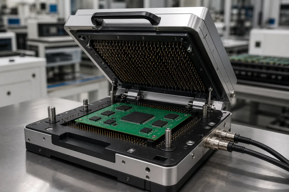
Electrical Test Fixture in a manufacturing environment
Representative product image. Confirm appearance and specifications with the manufacturer.

Product Specifications

Technical details and manufacturing context for Electrical Test Fixture

Definition
An electrical test fixture is a critical component within the Quality Verification Module that provides mechanical support and establishes reliable electrical connections between the device under test (DUT) and automated test equipment (ATE). It ensures precise alignment and consistent contact for accurate measurement of electrical parameters such as voltage, current, resistance, and signal integrity during quality control inspections. The fixture is designed for use in computer, electronic, and optical product manufacturing, where it facilitates the testing of printed circuit boards, electronic modules, and other assemblies. It is a part-level component, meaning it is a discrete unit that can be integrated into larger test systems. The fixture typically consists of a housing, a PCB substrate, and precision contact pins. The housing is commonly made of aluminum alloy, providing structural rigidity and protection. The PCB substrate, often FR-4, routes signals between the DUT and external test instruments. Contact pins are typically made of phosphor bronze, offering good conductivity and wear resistance. The fixture operates by aligning contact pins with test points on the DUT and applying controlled pressure to establish electrical continuity. This enables automated testing of circuit functionality, performance specifications, and defect detection. Key parameters include contact resistance (≤50 mΩ), insulation resistance (≥100 MΩ at 500 V DC), dielectric withstand voltage (1500 V AC for 1 minute), current rating (10–30 A per contact), operating temperature (-40 to 85 °C), humidity range (5–95% RH non-condensing), ingress protection (IP54–IP65 per IEC 60529), contact force (0.5–2.0 N per contact), cycle life (100,000–500,000 cycles), positioning accuracy (±0.05 mm), and fixture weight (5–20 kg). The frame material is aluminum 6061 per ASTM B209, while contacts are beryllium copper. These values are reference ranges and must be verified for the specific model and application. Always confirm model-specific values and standards with the legal manufacturer or supplier.
Working Principle
The fixture uses precision-machined contact pins or probes that align with test points on the DUT. When the DUT is loaded, the fixture applies controlled pressure to establish electrical continuity. It routes signals between the DUT and external test instruments through internal wiring, enabling automated testing of circuit functionality, performance specifications, and defect detection. The contact force is typically 0.5–2.0 N per contact, ensuring reliable connection without damaging the DUT. The fixture's positioning accuracy of ±0.05 mm ensures precise alignment. The design allows for repeated use, with a cycle life of 100,000–500,000 mechanical operations. The fixture operates within a temperature range of -40 to 85 °C and humidity range of 5–95% RH non-condensing. The ingress protection rating of IP54–IP65 provides dust and water resistance. The fixture's weight ranges from 5 to 20 kg, depending on size and material. The frame is made of aluminum 6061, and contacts are beryllium copper, offering good conductivity and durability.
Common Materials
Phosphor bronze (contact pins), FR-4 (PCB substrate), Aluminum alloy (housing)
Technical Parameters
ParameterTypical rangeNotes & selection driver
Contact Resistance≤50 Lower is better for reliable signal integrity
Insulation Resistance≥100 At 500 V DC
Dielectric Withstand Voltage1500 V ACFor 1 minute without breakdown
Current Rating10–30 APer contact
Operating Temperature-40–85 °CContinuous operation
Humidity Range5–95 % RHNon-condensing
Ingress ProtectionIP54–IP65Dust and water resistanceIEC 60529
Contact Force0.5–2.0 NPer contact
Cycle Life100000–500000 cyclesMechanical operations
Positioning Accuracy±0.05 mmRepeatability
Fixture Weight5–20 kgDepends on size and material
MaterialAluminum 6061Frame; contacts are beryllium copperASTM B209

Ranges are indicative industry figures for RFQ preparation, not a supplier commitment. Confirm every value and standard with the legal manufacturer before ordering.

Components / BOM
  • Contact Probe Array
    Establishes electrical connection with DUT test pads
    Material: Phosphor bronze with gold plating
  • Fixture Plate Part
    Provides structural support and DUT alignment
    Material: Aluminum alloy
  • Interface Connector Part
    Connects fixture to ATE system
    Material: High-density plastic with copper contacts
  • Internal Wiring
    Routes each probe to the right ATE channel inside the fixture.

Applied To / Applications

This component is essential for the following industrial systems and equipment:

Industrial Ecosystem & Supply Chain Structure

Complementary Systems
Downstream Applications
Specialized Tooling

Application Fit & Sizing Matrix

Operational Limits
pressure: Atmospheric to 5 psi
other spec: Max current: 50A, Max voltage: 1000V, Contact resistance: <10mΩ
temperature: -40°C to +125°C
Media Compatibility
✓ PCB assemblies ✓ Semiconductor packages ✓ Connector interfaces
Unsuitable: High-vibration or shock environments
Sizing Data Required
  • Component dimensions and pin count
  • Required test current and voltage
  • Interface type (pogo pins, sockets, clamps)

Reliability & Engineering Risk Analysis

Failure Mode & Root Cause
Intermittent Electrical Contact
Cause: Oxidation or contamination of test probe contacts due to environmental exposure, leading to inconsistent signal transmission and false test results.
Mechanical Fatigue of Fixture Components
Cause: Repeated insertion/removal cycles of test units causing wear on alignment pins, clamps, or connectors, eventually leading to misalignment or breakage.
Maintenance Indicators
  • Erratic or fluctuating test readings during operation, indicating potential contact issues
  • Unusual audible clicks, grinding, or resistance when inserting/removing test units, suggesting mechanical wear or misalignment
Engineering Tips
  • Implement regular cleaning and inspection of electrical contacts using appropriate contact cleaners and protective coatings to prevent oxidation
  • Establish a preventive maintenance schedule for mechanical components, including lubrication of moving parts and periodic alignment verification to reduce wear

Indicative industry ranges for design and RFQ preparation. Confirm the exact figures and applicable standard with the manufacturer before specifying.

Compliance & Manufacturing Standards

Applicable Standards
IEC 61010-1: Safety requirements for electrical equipment for measurement, control, and laboratory use UL 61010-1: Standard for Safety Requirements for Electrical Equipment for Measurement, Control, and Laboratory Use

Quoted from the published standard.

Manufacturing Precision
  • Contact alignment: +/-0.05mm
  • Insulation resistance: >100 MΩ at 500V DC
Quality Inspection
  • High-potential (hipot) test: Dielectric withstand voltage test
  • Continuity and resistance verification: Electrical circuit integrity test

Manufacturers of Electrical Test Fixture

Manufacturer profiles associated with Electrical Test Fixture.

Sourcing Electrical Test Fixture from China?
Tell us your specification and target quantity — we will match it against manufacturer records and come back with the factories that fit.
Request manufacturers We manufacture this

Manufacturer listings support early research and capability understanding. They are not certification, ranking, or transaction guarantees.

Share this page
Technical documentation
Request current drawings, revision history, and a signed specification sheet.
Manufacturing capability
Verify equipment lists, process limits, capacity, and representative production evidence.
Inspection readiness
Confirm test methods, calibrated equipment, sampling plans, and traceable reports.
Supplier transparency
Check the legal entity, factory address, ownership, certifications, and direct contacts.

CNFX does not score or rank suppliers. Buyers must verify all claims and documents with the legal manufacturer before ordering.

Supply Chain Compatible Machinery & Devices

Modular Industrial Edge Computing Device

This modular industrial edge computing device is a ruggedized system designed for deployment in harsh industrial environments to perform real-time data processing, analytics, and control functions at the network edge.

Explore Specs →
Industrial Smart Camera Module

The Industrial Smart Camera Module is a compact, self-contained vision processing unit designed for integration into industrial machinery and production lines.

Explore Specs →
Surface Mount Resistor

Passive electronic component for current limiting and voltage division in circuits

Explore Specs →
Surface Mount Capacitor

A surface mount capacitor is a fundamental electronic component used for energy storage, filtering, coupling, and decoupling in electronic circuits.

Explore Specs →

Frequently Asked Questions

What is the typical contact resistance of an electrical test fixture?

The contact resistance is typically ≤50 mΩ, which is lower for better signal integrity. This value is a reference range and should be verified for the specific model and application with the manufacturer or supplier.

What is the insulation resistance specification?

The insulation resistance is ≥100 MΩ at 500 V DC. This ensures adequate isolation between circuits. Confirm the exact value for your specific fixture model.

What is the dielectric withstand voltage rating?

The fixture can withstand 1500 V AC for 1 minute without breakdown. This is a safety parameter that should be verified for the specific fixture and test conditions.

What is the operating temperature range?

The operating temperature range is -40 to 85 °C for continuous operation. This range is a reference; always check the manufacturer's specifications for your specific fixture.

Data Basis

Editorial classification, named public sources where available, and source-reviewed manufacturer records.

Preliminary Technical Classification
This page supports structured research, RFQ preparation, and supplier evaluation. It does not replace buyer-led supplier qualification, standards review, or technical approval.
Buyer enquiry

Request manufacturing insight for Electrical Test Fixture

Ask for use case, specification boundaries, supplier type, and RFQ preparation information for this product.

Where it goes
Straight to the CNFX editorial desk, and to the manufacturer if this product is linked to a claimed profile. Nothing is broadcast to a supplier list.
Your details stay here
We do not sell or rent enquiry data, and we do not add you to a mailing list. Used only to answer this request.
No commission, no middleman
CNFX is a directory. We take no cut of any order and never negotiate on a supplier's behalf.
What we don't claim
A listing is not an endorsement. Qualify every supplier and verify every figure yourself before ordering.

Your business information is used only to process this request.

Thank you! Your message has been sent. We'll respond within 1–3 business days.
Sorry, we couldn't send your message. Please try again, or email us at [email protected].

Need to Manufacture Electrical Test Fixture?

Compare manufacturer profiles with relevant product and process capability.

Previous Product
XY Positioning Stage
Last Product
Get QuotesChat