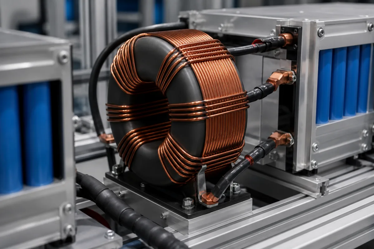
Balancing inductor and transformer: the magnetic energy-transfer element in active cell balancers
The inductor or transformer that carries charge between cells in an active balancer · turns ratio, primary inductance, leakage, winding resistance and peak current
An active cell balancer moves charge out of a high cell and into a low one (or into the whole stack) instead of burning it in a resistor, and the part that holds that energy between switching edges is a wound magnetic component: a single inductor, a coupled-inductor flyback transformer, or a forward transformer with an output choke. Its turns ratio, inductance, leakage, winding resistance and current rating are set by the balancing topology, the number of cells in the stack and the balancing current, so it is bought against a named balancer design rather than as a catalogue inductor.
Inductors, coupled inductors and transformers used as the energy-storage and transfer element in inductive and transformer-based active cell balancing circuits for series lithium-ion stacks. Complete battery management systems and protection boards are covered on the Battery management system page, and master–slave BMS architectures for module-based packs on the Distributed (master–slave) battery management system page. Balancer controller ICs, capacitor-based balancers, cells and storage cabinets are outside this page.
CNFX editorial research · Sources checked October 12, 2026 · 5 sources
Forward transformer between one cell and a 14-cell stack: 3.5:1 turns, at least 190 µH primary, leakage at or below 1%
In TI's switch-matrix scheme the EMB1499Q controller drives a bidirectional forward converter that exchanges energy between a single cell and the stack it belongs to, at a fixed 250 kHz and a stack voltage of up to 60 V; the EMB1428 switch-matrix driver routes the inductor current to the cell being charged or discharged, up to 7 cells per device. [1][2] The datasheet ties the transformer to the cell count: the turns ratio follows n = 0.25 × number of cells, giving 3.5:1 for a 14-cell stack, and the minimum primary inductance is 190 µH for 14 cells, scaled to 95 µH for 7. [1]
TI recommends leakage inductance of no more than 1% of the winding inductance, and for a 5 A design a primary DC winding resistance below a typical 60 mΩ and a secondary below a typical 12 mΩ, scaled for constant DC loss at other balancing currents. [1] The primary and secondary sense resistors are chosen with a ratio close to the turns ratio; the datasheet example pairs a 10 mΩ secondary resistor with about 35 mΩ on the primary for 3.5:1. [1]
On the cell side the converter's output inductor carries the balancing current itself. TI suggests an inductance that gives a peak-to-peak ripple of 20% to 40% of the steady-state balancing current, an inductor that does not saturate at peak current, and minimal DC winding resistance. [1] Each balancing burst runs at constant current for less than 8 s before the controller ramps the inductor current down, which takes about 300 µs. [1]
Editorial calculation: 190 × 12 / 14 ≈ 163 µH, using TI's statement that the value can be scaled with cell count
TI's design rules ask for primary MOSFETs and the clamp capacitor rated to at least 2.5 times the maximum stack voltage. [1] Editorial note: state the insulation required between the transformer windings against the stack voltage, not the cell voltage.
02
A 1:1 coupled flyback transformer of 3.4 µH, rated 10 A peak, for six-cell bidirectional balancers
Coilcraft's MA5421-AL was developed for Linear Technology's LTC3300-1 bidirectional cell balancer. It is a ferrite-core, two-winding part with a 1:1 turns ratio, 3.4 µH ±15% primary inductance at 0 A and at least 2.8 µH at its 10 A peak current, which Coilcraft defines as the peak primary current drawn at minimum input voltage. [3]
Leakage inductance is at most 0.15 µH, measured on the paralleled primary windings with the secondary shorted, and the DC resistance is 0.009 Ω on the primary and 0.011 Ω on the secondary. [3] Editorial calculation: 0.15 µH leakage against 3.4 µH nominal inductance is about 4.4%, so the 1% limit TI sets for its forward transformer is not a rule to carry over to flyback parts; state the limit for the design in hand.
One shared 33 µH inductor with a 1 µH / 1 µF resonant branch for direct cell-to-cell transfer
A TI patent describes a single-inductor approach in which each cell connects through a pair of back-to-back MOSFETs to one larger shared inductor, and a small series inductor, a capacitor and an extra switch form a resonant branch that reverses the current direction in the main inductor. In the embodiment given, the main inductor is 33 µH, the resonant inductor 1 µH and the capacitor 1 µF. [4]
Because energy goes from cell to cell without a transformer as a buffer, the patent states balancing efficiency of up to 85% or more, and it describes the arrangement as a low-cost option using one switch pair per channel and one larger inductor per group of cells. [4] The patent adds that the values it lists may be exact or approximate and relate to specific implementations. [4]
A multi-inductor scheme modelled in Scientific Reports gives a sense of how far model values can sit from the parts above: the authors used three 10 mH, 10 Ω inductors at 10 kHz and 50% duty on a pack of four 12.8 V, 40 Ah cells, with a maximum balancing current of 13.76 A, and tested it in MATLAB/Simulink and on an OPAL-RT 5700 hardware-in-the-loop simulator rather than with wound parts. [5] Its single-layer version balanced in 108 s in simulation and 110 s in HIL testing. [5]
04
Data for a balancing inductor or transformer enquiry
Paste it into your enquiry below or into an email to a maker, then replace every bracket.
Balancer: [controller IC or reference design; topology: forward, flyback, shared inductor]
Stack: [number of series cells; maximum stack voltage; cell chemistry and voltage window]
Current: [balancing current; peak current; RMS current; burst duration]
Magnetics: [turns ratio; primary inductance at 0 A and at peak current; leakage limit; DCR per winding]
Insulation: [isolation voltage between windings; creepage]
Environment: [ambient range; part temperature limit; mounting; weight]
12 companies list this product among what they make. Company figures are quoted from each
company's own website; every card states where the relationship came from.
Biglux Innovation Ltd
Shenzhen, Guangdong, CN
Listed on the company's own website · profile compiled by CNFX from public sources
Listed there as: “Mobile Energy Storage” View source page ↗bigluxled.com · recorded 2026-09-16
Explore company information and manufacturing capabilities, then discuss the scope of your project with a relevant supplier.
Share this page
Compiled and source-reviewed by the CNFX editorial team.
Each manufacturer above links to the page on that company's own website where the product is listed, with the date we checked it. How we source and review
· Page last updated 13 October 2026
Buyer questions
How is the turns ratio chosen for a forward-converter cell balancer?
In TI's EMB1499Q design it follows n = 0.25 × the number of cells, so 3.5:1 for 14 cells, with at least 190 µH primary inductance for 14 cells and 95 µH for 7. [1]
What does a flyback transformer for a six-cell bidirectional balancer look like?
Coilcraft's MA5421-AL for the LTC3300-1 is a 1:1 ferrite part with 3.4 µH primary inductance, 10 A peak and 3.3 A RMS current, and 1500 Vrms primary-to-secondary isolation. [3]
Can a single inductor balance cells without a transformer?
A TI patent describes a shared 33 µH inductor with a 1 µH, 1 µF resonant branch that reverses current direction, and states efficiency of up to 85% or more. [4]
How much leakage inductance is acceptable?
TI asks for leakage of no more than 1% of winding inductance in its forward transformer; Coilcraft's flyback part lists 0.15 µH maximum against 3.4 µH. [1][3]
Sources and what still needs a direct check
Sources checked 2026-10-12. Transformer and inductor rules for the forward-converter balancer come from TI's EMB1499Q and EMB1428Q datasheets; the flyback part ratings from Coilcraft's MA5421-AL datasheet; the shared-inductor values from a TI patent; and the modelled multi-inductor values from an open-access Scientific Reports paper. Values apply to the designs named.