Editorial Technical Reference

Microcontroller/MCU

This page explains how Microcontroller/MCU is classified within Computer, Electronic and Optical Product Manufacturing. Technical values and manufacturer relationships are research references; confirm the current specification and supplier evidence for each order.

Technical Definition & Core Assembly

A compact integrated circuit designed to govern specific operations within the Cell Monitoring Unit (CMU), executing programmed instructions to monitor and manage battery cell parameters.
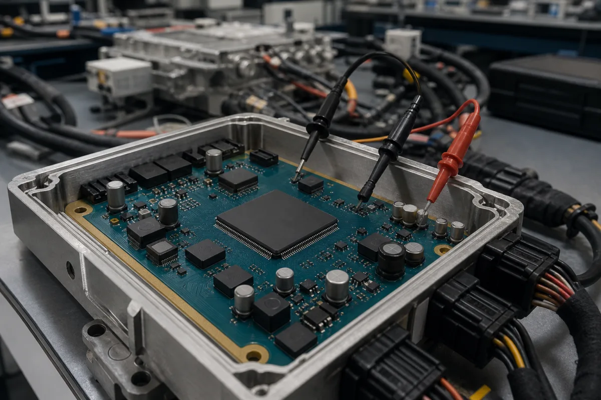
Representative product image. Confirm appearance and specifications with the manufacturer.

Product Specifications

Technical details and manufacturing context for Microcontroller/MCU

Definition
Within the Cell Monitoring Unit (CMU) of a battery management system (BMS), the microcontroller (MCU) serves as the central processing core. It is responsible for executing embedded firmware that orchestrates the CMU's primary functions: precisely measuring individual battery cell voltages and temperatures via connected sensors, performing analog-to-digital conversion, processing this data, and facilitating communication (e.g., via CAN, SPI, or I2C) with the Battery Management Controller (BMC) or other system modules. It ensures accurate, real-time monitoring critical for cell balancing, state-of-charge (SOC) estimation, and safety protection. The MCU is a component-level product, typically packaged in surface-mount form, and is selected based on parameters such as supply voltage, clock frequency, memory, ADC resolution, operating temperature, power consumption, package type, ESD rating, communication interfaces, GPIO pins, and standby current. These parameters are provided as reference ranges and must be verified against the specific model and application requirements. The MCU operates by fetching and executing instructions from its embedded flash memory, reading analog signals from sensors via integrated ADCs, processing data according to firmware algorithms, and triggering control signals for functions like passive cell balancing. It communicates with the main BMS controller via standard interfaces. The MCU is not a standalone product but a component intended for integration into a CMU PCB. It is not a manufacturer-specific product; rather, it is a generic category. For procurement, it is essential to confirm the exact specifications, compliance with relevant standards (e.g., IEC 61000-4-2 for ESD), and suitability for the intended automotive environment. The MCU's failure modes include firmware errors, electrical overstress, and thermal issues, which can be mitigated by proper design and testing. Maintenance signals include unexpected resets, communication errors, or inaccurate measurements. The MCU is not user-serviceable; replacement requires technical expertise. Always consult the legal manufacturer or supplier for model-specific values and standards.
Working Principle
The MCU operates by fetching and executing instructions from its embedded flash memory. It reads analog signals from cell voltage and temperature sensors through its integrated Analog-to-Digital Converters (ADCs). The digitized data is processed according to its firmware algorithms. Based on this data and predefined thresholds, it can trigger control signals for functions like passive cell balancing (activating discharge resistors) and transmit status information via its communication peripherals to the main BMS controller.
Common Materials
Silicon (Semiconductor wafer), Copper (Interconnects), Plastic (Package molding compound)
Technical Parameters
ParameterTypical rangeNotes & selection driver
Supply Voltage2.7–5.5 V DCOperating range for core logic and I/O
Clock Frequency16–80 MHzHigher frequency enables faster processing
Flash Memory32–512 KBStores firmware and calibration data
SRAM4–64 KBFor runtime data and stack
ADC Resolution12–16 bitHigher resolution improves measurement precision
Operating Temperature-40–85 °CAutomotive grade range
Power Consumption10–100 mWAt 3.3 V, active mode
Package TypeQFN-32–LQFP-64Footprint options for PCB design
ESD Rating±2–±4 kVHBM modelIEC 61000-4-2
Communication Interfaces2–4 channelsCAN, SPI, I2C, UART
GPIO Pins16–48 pinsConfigurable digital I/O
Supply Current (Standby)1–10 µALow-power mode for battery preservation

Ranges are indicative industry figures for RFQ preparation, not a supplier commitment. Confirm every value and standard with the legal manufacturer before ordering.

Components / BOM
  • Central Processing Unit (CPU) Core Part
    Executes the firmware instructions, performs arithmetic/logic operations, and manages data flow for cell monitoring tasks.
    Material: Silicon
  • Analog-to-Digital Converter (ADC)
    Converts analog signals from cell voltage sensors and thermistors into digital values for processing by the CPU.
    Material: Silicon
  • Flash Memory Part
    Stores the non-volatile firmware code and calibration constants for the CMU application.
    Material: Silicon (floating-gate transistors)
  • Serial Communication Peripheral (e.g., CAN Controller) Part
    Handles the protocol-specific communication (e.g., message framing, error checking) for transmitting cell data to the main BMS controller.
    Material: Silicon
  • General-Purpose Input/Output (GPIO) Pins Part
    Provide digital control signals, for example, to enable/disable cell balancing circuits or read digital status lines.
    Material: Copper (bond wires, package leads)

Applied To / Applications

This component is essential for the following industrial systems and equipment:

Industrial Ecosystem & Supply Chain Structure

Complementary Systems
Downstream Applications
Specialized Tooling

Application Fit & Sizing Matrix

Operational Limits
voltage: 1.8V to 5.5V supply range, 3.3V typical
clock speed: Up to 200 MHz core frequency
temperature: -40°C to +125°C (operating), -55°C to +150°C (storage)
power consumption: Active: < 100 µA/MHz, Sleep: < 2 µA, Deep Sleep: < 200 nA
Media Compatibility
✓ Lithium-ion battery management systems ✓ Automotive CAN bus networks ✓ Industrial 4-20mA sensor interfaces
Unsuitable: High-voltage arc discharge environments (> 1kV transient spikes)
Sizing Data Required
  • Required ADC resolution and sampling rate for cell voltage monitoring
  • Number of communication interfaces (CAN, SPI, I2C) needed for CMU network
  • Real-time processing requirements for cell balancing algorithms

Reliability & Engineering Risk Analysis

Failure Mode & Root Cause
Electrostatic Discharge (ESD) Damage
Cause: Improper handling without ESD protection, leading to internal gate oxide breakdown or latch-up in semiconductor junctions.
Thermal Overstress
Cause: Excessive ambient temperature, inadequate cooling, or high current draw causing silicon degradation, solder joint failure, or timing errors.
Maintenance Indicators
  • Intermittent or erratic system behavior (e.g., random resets, data corruption) under normal operating conditions.
  • Visible physical damage such as discoloration (browning/yellowing), bulging, or charring on the MCU package or nearby components.
Engineering Tips
  • Implement strict ESD controls: use grounded workstations, wrist straps, and anti-static packaging during handling and installation.
  • Ensure proper thermal management: design with adequate heatsinking, maintain clean airflow, and avoid exceeding the MCU's specified junction temperature in the application.

Indicative industry ranges for design and RFQ preparation. Confirm the exact figures and applicable standard with the manufacturer before specifying.

Compliance & Manufacturing Standards

Applicable Standards
IEC 60747-8 - Semiconductor devices - Integrated circuits - Microcontrollers CE Marking - EU Directive 2014/35/EU (Low Voltage Directive)

Quoted from the published standard.

Manufacturing Precision
  • Clock Frequency Stability: +/- 0.5% over operating temperature range
  • Supply Voltage Tolerance: +/- 5% of nominal voltage
Quality Inspection
  • Automated Optical Inspection (AOI) for solder joints and component placement
  • Environmental Stress Screening (ESS) including temperature cycling and burn-in testing

Manufacturers of Microcontroller/MCU

Manufacturer profiles associated with Microcontroller/MCU.

Sourcing Microcontroller/MCU from China?
Tell us your specification and target quantity — we will match it against manufacturer records and come back with the factories that fit.
Request manufacturers We manufacture this

Manufacturer listings support early research and capability understanding. They are not certification, ranking, or transaction guarantees.

Technical documentation
Request current drawings, revision history, and a signed specification sheet.
Manufacturing capability
Verify equipment lists, process limits, capacity, and representative production evidence.
Inspection readiness
Confirm test methods, calibrated equipment, sampling plans, and traceable reports.
Supplier transparency
Check the legal entity, factory address, ownership, certifications, and direct contacts.

CNFX does not score or rank suppliers. Buyers must verify all claims and documents with the legal manufacturer before ordering.

Supply Chain Compatible Machinery & Devices

Industrial Smart Camera Module

The Industrial Smart Camera Module is a compact, self-contained vision processing unit designed for integration into industrial machinery and production lines.

Explore Specs →
Surface Mount Resistor

Passive electronic component for current limiting and voltage division in circuits

Explore Specs →
Surface Mount Capacitor

A surface mount capacitor is a fundamental electronic component used for energy storage, filtering, coupling, and decoupling in electronic circuits.

Explore Specs →
Surface Mount Technology (SMT) Pick-and-Place Machine

Automated machine that precisely places electronic components onto printed circuit boards.

Explore Specs →

Frequently Asked Questions

What is the primary function of an MCU in a CMU?

The MCU executes firmware to measure cell voltages and temperatures, perform analog-to-digital conversion, process data, and communicate with the BMC or other modules. It enables real-time monitoring for cell balancing, SOC estimation, and safety.

What are typical supply voltage and clock frequency ranges?

Typical supply voltage is 2.7–5.5 V DC, and clock frequency ranges from 16 to 80 MHz. These are reference ranges; actual values depend on the specific MCU model and application.

How does the MCU communicate with the main BMS controller?

It uses standard communication interfaces such as CAN, SPI, I2C, or UART. The number of channels typically ranges from 2 to 4, depending on the model.

What should be verified before selecting an MCU for a CMU?

Verify all parameters (supply voltage, clock, memory, ADC resolution, temperature range, power, package, ESD rating, interfaces, GPIO, standby current) against the application requirements. Also confirm compliance with relevant standards, such as IEC 61000-4-2 for ESD, with the legal manufacturer or supplier.

Data Basis

Editorial classification, named public sources where available, and source-reviewed manufacturer records.

Preliminary Technical Classification
This page supports structured research, RFQ preparation, and supplier evaluation. It does not replace buyer-led supplier qualification, standards review, or technical approval.
Buyer enquiry

Request manufacturing insight for Microcontroller/MCU

Ask for use case, specification boundaries, supplier type, and RFQ preparation information for this product.

Where it goes
Straight to the CNFX editorial desk, and to the manufacturer if this product is linked to a claimed profile. Nothing is broadcast to a supplier list.
Your details stay here
We do not sell or rent enquiry data, and we do not add you to a mailing list. Used only to answer this request.
No commission, no middleman
CNFX is a directory. We take no cut of any order and never negotiate on a supplier's behalf.
What we don't claim
A listing is not an endorsement. Qualify every supplier and verify every figure yourself before ordering.

Your business information is used only to process this request.

Thank you! Your message has been sent. We'll respond within 1–3 business days.
Sorry, we couldn't send your message. Please try again, or email us at contact@cnfx.com.

Need to Manufacture Microcontroller/MCU?

Compare manufacturer profiles with relevant product and process capability.

Previous Product
XY Positioning Stage
Last Product
Get QuotesChat