Editorial Technical Reference

Position Locking Mechanism

This page explains how Position Locking Mechanism is classified within Computer, Electronic and Optical Product Manufacturing. Technical values and manufacturer relationships are research references; confirm the current specification and supplier evidence for each order.

Technical Definition & Core Assembly

A mechanical component that securely fixes the antenna in its optimal position within the mounting system.
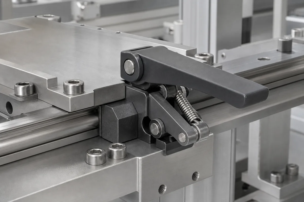
Representative product image. Confirm appearance and specifications with the manufacturer.

Product Specifications

Technical details and manufacturing context for Position Locking Mechanism

Definition
The Position Locking Mechanism is a critical component of the Internal Antenna Mounting System. Its primary function is to ensure that the antenna remains precisely positioned after installation, preventing movement, vibration, or displacement that could degrade signal quality. By maintaining alignment with external communication networks, this mechanism contributes to consistent performance in demanding environments. The mechanism is designed to operate within specified mechanical and environmental parameters, which must be verified for each specific application. It is typically constructed from stainless steel or aluminum alloy, with the aluminum variant often featuring an anodized surface treatment. Key performance parameters include locking torque, release torque, axial and radial load capacities, operating temperature range, ingress protection rating, and cycle life. These values are provided as reference ranges and must be confirmed with the manufacturer for the exact model. The mechanism is intended for use in computer, electronic, and optical product manufacturing, particularly in antenna mounting systems. It is a component-level product, not a standalone device. Proper installation and maintenance are essential to ensure reliable operation. Users should verify that the selected mechanism meets the required specifications for their specific application, including load, torque, and environmental conditions. The mechanism's design incorporates a cam, latch, or screw-based system that engages with mounting brackets or rails, creating mechanical interference or friction to prevent movement. Spring-loaded components or threaded fasteners maintain consistent locking pressure. The mechanism is not a safety device and should not be used as such. It is designed for industrial applications and should be installed by qualified personnel. Regular inspection and testing are recommended to ensure continued performance. The manufacturer or supplier should be consulted for detailed technical data and installation guidelines.
Working Principle
The mechanism typically employs a cam, latch, or screw-based system that engages with mounting brackets or rails. When activated, it creates mechanical interference or friction that prevents movement, often using spring-loaded components or threaded fasteners to maintain consistent locking pressure. The locking action secures the antenna in place, while the release action allows for adjustment or removal. The design ensures that the locking torque is sufficient to hold the antenna under vibration, but the release torque is higher to prevent accidental release. The mechanism's load capacity and environmental resistance are defined by its materials and surface treatment.
Common Materials
Stainless Steel, Aluminum Alloy
Technical Parameters
ParameterTypical rangeNotes & selection driver
Locking Torque5–15 N·mEnsures secure positioning under vibration
Release Torque8–20 N·mMust be higher than locking torque to avoid accidental release
Axial Load Capacity500–2000 NMaximum force along the axis without failure
Radial Load Capacity300–1000 NMaximum force perpendicular to the axis
Operating Temperature-40–85 °COutside this range, material properties degrade
Ingress ProtectionIP54–IP65Protection against dust and water jetsIEC 60529
Material6061-T6Aluminum alloy with high strength-to-weight ratioASTM B221
Surface TreatmentAnodizedType II, class 2, 18–20 μm thicknessMIL-A-8625
Weight0.15–0.35 kgDepends on size and material
Dimensions50×30×20–80×50×40 mmLength × width × height
Cycle Life10000–50000 cyclesNumber of lock/unlock operations
Vibration Resistance10–2000 HzSinusoidal vibration, 10 g accelerationIEC 60068-2-6

Ranges are indicative industry figures for RFQ preparation, not a supplier commitment. Confirm every value and standard with the legal manufacturer before ordering.

Components / BOM
  • Locking Cam Part
    Creates mechanical interference to prevent movement
    Material: Stainless Steel
  • Spring Mechanism Part
    Provides consistent locking pressure
    Material: Spring Steel
  • Actuation Lever Part
    Manual control for engaging/disengaging the lock
    Material: Aluminum Alloy

Applied To / Applications

This component is essential for the following industrial systems and equipment:

Industrial Ecosystem & Supply Chain Structure

Complementary Systems
Downstream Applications
Specialized Tooling

Application Fit & Sizing Matrix

Operational Limits
pressure: 0 to 100 kPa (atmospheric to slight positive pressure)
other spec: Vibration resistance: 5-2000 Hz, 10 g RMS
temperature: -40°C to +85°C
Media Compatibility
✓ Outdoor atmospheric air ✓ Marine-grade aluminum housings ✓ UV-resistant polymer coatings
Unsuitable: High-pressure washdown or submerged environments
Sizing Data Required
  • Antenna weight and moment load
  • Mounting interface dimensions and bolt pattern
  • Required angular adjustment range and locking resolution

Reliability & Engineering Risk Analysis

Failure Mode & Root Cause
Wear-induced slippage
Cause: Gradual material degradation from repeated engagement cycles under load, leading to loss of precise positioning capability.
Corrosion or contamination jamming
Cause: Environmental exposure (moisture, chemicals) or ingress of particulate matter causing seizure or restricted movement.
Maintenance Indicators
  • Audible grinding or scraping during engagement/disengagement
  • Visible misalignment or excessive play in the locked position
Engineering Tips
  • Implement regular lubrication with compatible anti-wear compounds and establish contamination control protocols.
  • Conduct periodic alignment verification and torque/force calibration to ensure proper engagement parameters.

Indicative industry ranges for design and RFQ preparation. Confirm the exact figures and applicable standard with the manufacturer before specifying.

Compliance & Manufacturing Standards

Applicable Standards
ISO 286-2:2010 - Limits and fits ANSI B4.2-1978 - Preferred metric limits and fits DIN 7182-1 - Tolerances for linear dimensions

Quoted from the published standard.

Manufacturing Precision
  • Bore diameter: +/-0.02mm
  • Surface flatness: 0.1mm
Quality Inspection
  • Dye Penetrant Test for surface defects
  • Coordinate Measuring Machine (CMM) dimensional verification

Manufacturers of Position Locking Mechanism

Manufacturer profiles associated with Position Locking Mechanism.

Sourcing Position Locking Mechanism from China?
Tell us your specification and target quantity — we will match it against manufacturer records and come back with the factories that fit.
Request manufacturers We manufacture this

Manufacturer listings support early research and capability understanding. They are not certification, ranking, or transaction guarantees.

Technical documentation
Request current drawings, revision history, and a signed specification sheet.
Manufacturing capability
Verify equipment lists, process limits, capacity, and representative production evidence.
Inspection readiness
Confirm test methods, calibrated equipment, sampling plans, and traceable reports.
Supplier transparency
Check the legal entity, factory address, ownership, certifications, and direct contacts.

CNFX does not score or rank suppliers. Buyers must verify all claims and documents with the legal manufacturer before ordering.

Supply Chain Compatible Machinery & Devices

Modular Industrial Edge Computing Device

This modular industrial edge computing device is a ruggedized system designed for deployment in harsh industrial environments to perform real-time data processing, analytics, and control functions at the network edge.

Explore Specs →
Industrial Smart Camera Module

The Industrial Smart Camera Module is a compact, self-contained vision processing unit designed for integration into industrial machinery and production lines.

Explore Specs →
Surface Mount Resistor

Passive electronic component for current limiting and voltage division in circuits

Explore Specs →
Surface Mount Capacitor

A surface mount capacitor is a fundamental electronic component used for energy storage, filtering, coupling, and decoupling in electronic circuits.

Explore Specs →

Frequently Asked Questions

What is the purpose of the Position Locking Mechanism?

It securely fixes the antenna in its optimal position within the mounting system, preventing movement or vibration that could degrade signal quality.

What materials are used for this mechanism?

The materials on file are stainless steel and aluminum alloy. The aluminum alloy may be anodized for surface protection.

What are the key performance parameters?

Key parameters include locking torque (5–15 N·m), release torque (8–20 N·m), axial load capacity (500–2000 N), radial load capacity (300–1000 N), operating temperature (-40 to 85 °C), ingress protection (IP54–IP65), and cycle life (10,000–50,000 cycles). These are reference ranges and must be confirmed for the specific model.

How should I verify that this mechanism meets my requirements?

You should consult the manufacturer or supplier to confirm that the model-specific values for torque, load, temperature, and other parameters meet your application needs. Also, verify compliance with relevant standards such as IEC 60529 for ingress protection.

Data Basis

Editorial classification, named public sources where available, and source-reviewed manufacturer records.

Preliminary Technical Classification
This page supports structured research, RFQ preparation, and supplier evaluation. It does not replace buyer-led supplier qualification, standards review, or technical approval.
Buyer enquiry

Request manufacturing insight for Position Locking Mechanism

Ask for use case, specification boundaries, supplier type, and RFQ preparation information for this product.

Where it goes
Straight to the CNFX editorial desk, and to the manufacturer if this product is linked to a claimed profile. Nothing is broadcast to a supplier list.
Your details stay here
We do not sell or rent enquiry data, and we do not add you to a mailing list. Used only to answer this request.
No commission, no middleman
CNFX is a directory. We take no cut of any order and never negotiate on a supplier's behalf.
What we don't claim
A listing is not an endorsement. Qualify every supplier and verify every figure yourself before ordering.

Your business information is used only to process this request.

Thank you! Your message has been sent. We'll respond within 1–3 business days.
Sorry, we couldn't send your message. Please try again, or email us at contact@cnfx.com.

Need to Manufacture Position Locking Mechanism?

Compare manufacturer profiles with relevant product and process capability.

Previous Product
XY Positioning Stage
Last Product
Get QuotesChat