Editorial Technical Reference

Probe head interface

This page explains how Probe head interface is classified within Computer, Electronic and Optical Product Manufacturing. Technical values and manufacturer relationships are research references; confirm the current specification and supplier evidence for each order.

Technical Definition & Core Assembly

Electrical and mechanical connection point between the multi-sensor probe head and external systems.
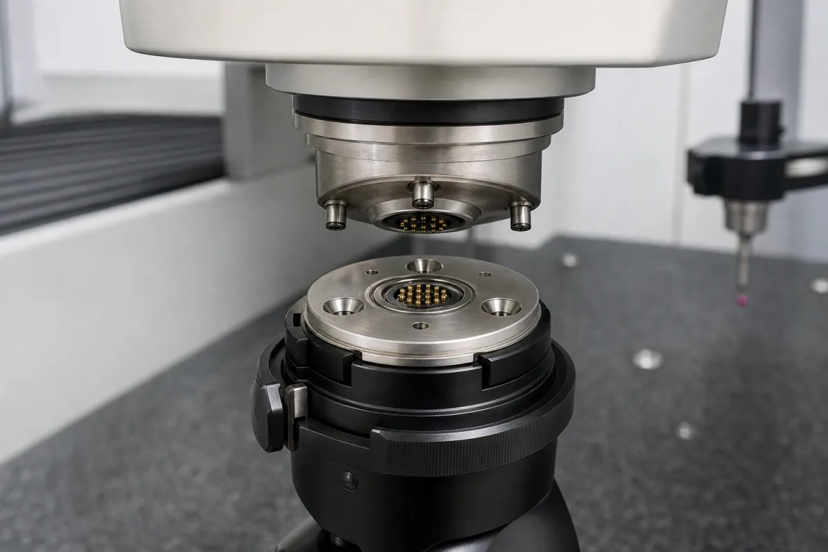
Representative product image. Confirm appearance and specifications with the manufacturer.

Product Specifications

Technical details and manufacturing context for Probe head interface

Definition
The probe head interface serves as the critical connection hub within a multi-sensor probe head, facilitating the transmission of power, control signals, and data between the probe's internal sensors (e.g., temperature, pressure, flow) and external monitoring, control, or data acquisition units. It ensures signal integrity, provides physical mounting, and often includes features for environmental sealing and electrical isolation. The interface typically consists of a multi-pin connector (electrical) and a mounting flange (mechanical). Electrically, it routes analog or digital signals from the embedded sensors to external cables. Mechanically, it provides a secure, aligned, and often sealed attachment point for the probe head to its housing or process connection. Materials on file include stainless steel for the housing, gold-plated brass for contacts, and silicone rubber for seals. Key parameters to verify for a specific model include number of pins (12–24), rated current per pin (1–3 A), rated voltage (24–60 V DC), contact resistance (≤10 mΩ), insulation resistance (≥100 MΩ at 500 V DC), operating temperature (-40 to 85 °C), IP rating (IP54–IP65 per IEC 60529), mating cycles (500–1000), connector type (M12–M16 per IEC 61076-2-101), housing material (stainless steel 304 per ASTM A276), and weight (50–150 g). These values are reference ranges; always confirm with the manufacturer for the intended application. The interface is designed for industrial environments, but its performance depends on correct installation and maintenance. Verify that the connector type and pin configuration match the mating cable and that the IP rating suits the environmental exposure. Regular inspection for seal integrity and contact wear is recommended. Failure to maintain proper sealing or electrical isolation can lead to signal degradation or equipment damage.
Working Principle
The interface provides a standardized electrical and mechanical connection. Electrically, it uses a multi-pin connector to route power and signals between the probe's sensors and external systems. Each pin is rated for a certain current and voltage, and contact resistance is kept low to preserve signal integrity. Mechanically, a mounting flange ensures secure attachment and alignment, with seals providing environmental protection. The design allows for repeated mating cycles, and the connector type (e.g., M12) ensures compatibility with standard cables.
Common Materials
Stainless Steel (housing), Gold-plated Brass (contacts), Silicone Rubber (seals)
Technical Parameters
ParameterTypical rangeNotes & selection driver
Number of Pins12–24 pinsDetermines signal and power capacity.
Rated Current per Pin1–3 AHigher current requires larger pin gauge.
Rated Voltage24–60 V DCExceeding may cause arcing or insulation failure.
Contact Resistance≤10 Lower is better for signal integrity.
Insulation Resistance≥100 At 500 V DC test voltage.
Operating Temperature-40–85 °COutside range may affect sealing and materials.
IP RatingIP54–IP65Higher rating for dusty or wet environments.IEC 60529
Mating Cycles500–1000 cyclesAffects long-term reliability.
Connector TypeM12–M16Thread size determines mechanical fit.IEC 61076-2-101
Housing MaterialStainless steel 304Corrosion resistance for industrial environments.ASTM A276
Weight50–150 gAffects probe head dynamics.

Ranges are indicative industry figures for RFQ preparation, not a supplier commitment. Confirm every value and standard with the legal manufacturer before ordering.

Components / BOM
  • Connector Body Part
    Houses the electrical contacts and provides structural integrity and environmental sealing.
    Material: Stainless Steel or Engineering Plastic
  • Contact Pins/Sockets Part
    Provide the electrical conduction path for signals and power.
    Material: Gold-plated Brass or Phosphor Bronze
  • Sealing Gasket/O-ring Part
    Creates a seal between the interface and its mating part to prevent ingress of fluids or contaminants.
    Material: Silicone Rubber, Viton, or EPDM
  • Mounting Flange
    The mechanical half of the interface — it locates and secures the probe head.

Applied To / Applications

This component is essential for the following industrial systems and equipment:

Industrial Ecosystem & Supply Chain Structure

Complementary Systems
Downstream Applications
Specialized Tooling

Application Fit & Sizing Matrix

Operational Limits
pressure: 0 to 10 bar
flow rate: 0 to 5 m/s
temperature: -20°C to 85°C
slurry concentration: 0 to 30% solids by weight
Media Compatibility
✓ Clean process water ✓ Non-corrosive chemical solutions ✓ Oil-based fluids
Unsuitable: High-concentration abrasive slurries with particles >100 microns
Sizing Data Required
  • Probe head connector type and pin count
  • Required cable length and bend radius
  • Environmental sealing/IP rating requirement

Reliability & Engineering Risk Analysis

Failure Mode & Root Cause
Electrical contact degradation
Cause: Oxidation or contamination of mating surfaces due to environmental exposure, improper sealing, or incompatible materials leading to increased resistance and signal loss
Mechanical misalignment
Cause: Vibration-induced loosening of fasteners, thermal expansion mismatches, or improper installation causing poor connection integrity and intermittent signal transmission
Maintenance Indicators
  • Intermittent or unstable signal output during operation
  • Visible corrosion, discoloration, or physical damage at the interface mating surfaces
Engineering Tips
  • Implement regular contact resistance testing and cleaning protocols using appropriate contact cleaners and protective coatings compatible with the operating environment
  • Use anti-vibration fasteners and torque monitoring during installation, along with periodic alignment verification using precision measurement tools

Indicative industry ranges for design and RFQ preparation. Confirm the exact figures and applicable standard with the manufacturer before specifying.

Compliance & Manufacturing Standards

Applicable Standards
ISO 10360-2:2009 (Geometrical product specifications - Acceptance and reverification tests for coordinate measuring machines) ANSI/ASME B89.1.12 (Dimensional Measuring Equipment - Probe Heads) DIN 32877 (Metrological characteristics of touch trigger probes for coordinate measuring machines)

Quoted from the published standard.

Manufacturing Precision
  • Probe tip sphericity: +/-0.0005mm
  • Mounting interface flatness: 0.002mm
Quality Inspection
  • Laser interferometer calibration test
  • Repeatability test under varying temperature conditions

Manufacturers of Probe head interface

Manufacturer profiles associated with Probe head interface.

Sourcing Probe head interface from China?
Tell us your specification and target quantity — we will match it against manufacturer records and come back with the factories that fit.
Request manufacturers We manufacture this

Manufacturer listings support early research and capability understanding. They are not certification, ranking, or transaction guarantees.

Technical documentation
Request current drawings, revision history, and a signed specification sheet.
Manufacturing capability
Verify equipment lists, process limits, capacity, and representative production evidence.
Inspection readiness
Confirm test methods, calibrated equipment, sampling plans, and traceable reports.
Supplier transparency
Check the legal entity, factory address, ownership, certifications, and direct contacts.

CNFX does not score or rank suppliers. Buyers must verify all claims and documents with the legal manufacturer before ordering.

Supply Chain Compatible Machinery & Devices

Industrial Smart Camera Module

The Industrial Smart Camera Module is a compact, self-contained vision processing unit designed for integration into industrial machinery and production lines.

Explore Specs →
Surface Mount Resistor

Passive electronic component for current limiting and voltage division in circuits

Explore Specs →
Surface Mount Capacitor

A surface mount capacitor is a fundamental electronic component used for energy storage, filtering, coupling, and decoupling in electronic circuits.

Explore Specs →
Surface Mount Technology (SMT) Pick-and-Place Machine

Automated machine that precisely places electronic components onto printed circuit boards.

Explore Specs →

Frequently Asked Questions

What is the purpose of the probe head interface?

It provides the electrical and mechanical connection between the multi-sensor probe head and external systems, enabling power, signal, and data transmission while ensuring physical mounting and environmental sealing.

What parameters should be verified before selecting an interface?

Key parameters include number of pins, rated current and voltage, contact resistance, insulation resistance, operating temperature, IP rating, mating cycles, connector type, housing material, and weight. Always confirm these with the manufacturer for your specific application.

How does the interface ensure signal integrity?

It uses low contact resistance (≤10 mΩ) and proper insulation (≥100 MΩ) to minimize signal loss and prevent electrical interference. The connector design also maintains consistent contact pressure.

What maintenance is required for the interface?

Regularly inspect seals for damage, check contacts for wear or corrosion, and ensure the connector is properly mated. Replace worn seals or contacts as needed to maintain IP rating and electrical performance.

Data Basis

Editorial classification, named public sources where available, and source-reviewed manufacturer records.

Preliminary Technical Classification
This page supports structured research, RFQ preparation, and supplier evaluation. It does not replace buyer-led supplier qualification, standards review, or technical approval.
Buyer enquiry

Request manufacturing insight for Probe head interface

Ask for use case, specification boundaries, supplier type, and RFQ preparation information for this product.

Where it goes
Straight to the CNFX editorial desk, and to the manufacturer if this product is linked to a claimed profile. Nothing is broadcast to a supplier list.
Your details stay here
We do not sell or rent enquiry data, and we do not add you to a mailing list. Used only to answer this request.
No commission, no middleman
CNFX is a directory. We take no cut of any order and never negotiate on a supplier's behalf.
What we don't claim
A listing is not an endorsement. Qualify every supplier and verify every figure yourself before ordering.

Your business information is used only to process this request.

Thank you! Your message has been sent. We'll respond within 1–3 business days.
Sorry, we couldn't send your message. Please try again, or email us at contact@cnfx.com.

Need to Manufacture Probe head interface?

Compare manufacturer profiles with relevant product and process capability.

Previous Product
XY Positioning Stage
Last Product
Get QuotesChat