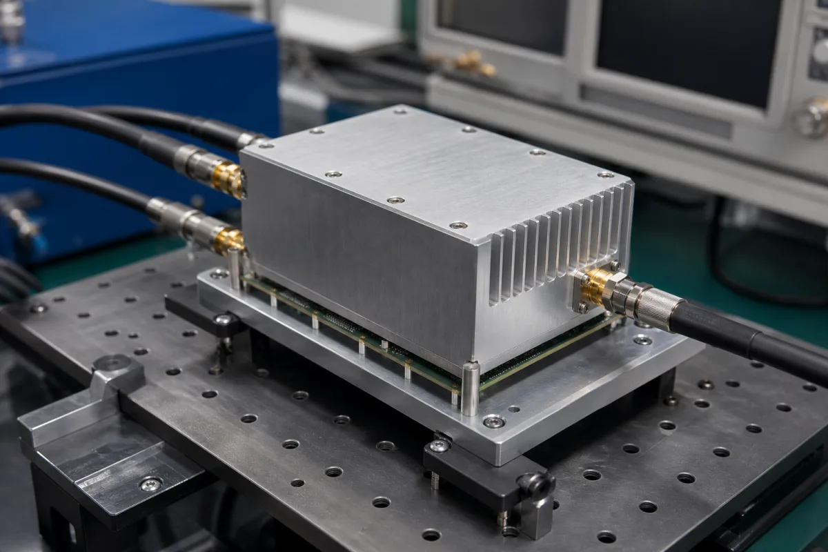
RF driver amplifier for electro-optic modulators: broadband 50 kHz–40 GHz amplifiers with 6–9 Vpp output
The broadband RF amplifier that drives a lithium niobate electro-optic modulator · output swing against the modulator's Vπ, bandwidth from kHz to tens of GHz, and edge speed
A lithium niobate electro-optic modulator is specified by its RF half-wave voltage Vπ, a few volts, while the drivers below expect an input of only 0.5 to 1 V. The modulator driver is the broadband RF amplifier between them: flat gain from tens of kilohertz up to the modulator's bandwidth, a maximum output of 6.3 to 9 volts peak to peak into 50 Ω, fast edges for digital data, and controls for gain and crossing point. This page sets driver output against modulator Vπ and RF power limits.
Broadband RF amplifiers built as drivers for LiNbO3 and similar electro-optic modulators in optical transmitters, microwave photonics and fibre sensing: module and benchtop versions with output swing in Vpp, gain control and crossing-point control. Solid-state RF power amplifier modules used as output stages in signal generators, test systems and transmitters are covered on the RF output stage amplifier page; low-noise amplifiers have their own page; RF transceiver and amplifier chips are covered on the RF integrated circuits (RFICs) page; CATV distribution amplifiers are outside this page.
CNFX editorial research · Sources checked October 12, 2026 · 4 sources
Output swing: 6.3–9 Vpp from the driver for a modulator whose Vπ is 2.5–3 V
Rofea's R-AM-08-10G, an 850 nm intensity modulator with a 10–12 GHz −3 dB bandwidth, lists an RF half-wave voltage Vπ of 2.5 to 3 V at 1 kHz, a 50 Ω RF input and an input RF power limit of 28 dBm. [4] Exail's DR-DG-12-MO driver gives 28 dB small-signal gain and a typical 23 dBm saturated output at 0.5 Vpp input; its summary says it delivers up to 9 Vpp, while its electrical table lists 2 to 8 Vpp output. [1] The DR-DG-40-MO gives 6.3 Vpp, 26 dB gain and at least 20 dBm saturated power. [2]
Editorial calculation: Vpp = 2√2 × √(P × 50 Ω) for a sine wave, with P in watts; 20 dBm (0.1 W) gives about 6.3 Vpp and 23 dBm about 8.9 Vpp, which matches the drivers' stated swings. A 2.5–3 V Vπ is therefore within the output range of each driver listed, and the modulator's 28 dBm RF input limit corresponds to about 15.9 Vpp, above any of these drivers' saturated output.
The two Exail figures for the DR-DG-12-MO (9 Vpp in the summary, 8 Vpp maximum in the table) should be settled with the supplier for the unit ordered. [1]
Driver
Output as stated
Power as stated
Editorial calculation: sine Vpp into 50 Ω at that power
State the modulator's Vπ at the operating frequency and its maximum RF input; the driver's output and gain setting are chosen from those.
02
Bandwidth from 50 kHz and edges of 9–22 ps for 10–44 Gbit/s data
Exail gives the DR-DG-12-MO a lower −3 dB point of 50 kHz, an upper −3 dB point of 15 GHz, gain ripple of ±1.5 dB below 15 GHz, 12/16 ps rise and fall and a noise figure of 3.5 to 6 dB from 1 to 20 GHz. [1] The DR-DG-40-MO covers 50 kHz to 40 GHz for 40–44 Gbit/s with 9 ps typical and 12 ps maximum rise and fall time and 0.75 ps added jitter. [2]
Exail's DR-DG-12-MO runs from a single 12 V supply at 260 mA typical, dissipates 3.2 W at 8 Vpp output and is rated for 0 to +40 °C, with an optional heat sink; its added-jitter figure is given as 0.9 fs in the summary and 850 fs in the electrical table. [1] Rofea's R-RF-10, R-RF-20 and R-RF-40 are benchtop units of 270 × 200 × 70 mm on 220 V AC with 0.5–1 V input amplitude, and the R-RF-10 is rated −10 to 60 °C. [3]
Editorial calculation: 12 V × 0.26 A ≈ 3.1 W drawn by the DR-DG-12-MO, consistent with the 3.2 W dissipation Exail lists at full swing.
Paste it into your enquiry below or into an email to a maker, then replace every bracket.
Modulator: [type; Vπ at the operating frequency; bandwidth; maximum RF input in dBm; connector]
Signal: [NRZ, RZ, analogue or pulse; data rate or frequency range; input level in Vpp]
Driver: [output Vpp; gain and crossing-point control; rise/fall time; jitter]
Package: [module with heat sink or benchtop; supply voltage; operating temperature]
1 company lists this product among what they make. Company figures are quoted from each
company's own website; every card states where the relationship came from.
Beijing Rofea Optoelectronics Co., Ltd.
Manufacturing site to be confirmed for the order
Lists R-RF-10, R-RF-20 and R-RF-40 broadband microwave amplifiers designed to drive LiNbO3 electro-optic modulators, alongside its intensity and phase modulators.
Explore company information and manufacturing capabilities, then discuss the scope of your project with a relevant supplier.
Share this page
Compiled and source-reviewed by the CNFX editorial team.
Each manufacturer above links to the page on that company's own website where the product is listed, with the date we checked it. How we source and review
· Page last updated 13 October 2026
Buyer questions
How many volts does a modulator driver deliver?
The drivers compared give 6.3 to 9 Vpp: Exail's DR-DG-40-MO 6.3 Vpp and DR-DG-12-MO up to 9 Vpp (8 Vpp in its table), Rofea's R-RF-10 3.5 to 8 V. [2][1][3]
How do I convert driver output power to volts?
Editorial calculation for a sine into 50 Ω: Vpp = 2√2 × √(P × 50); 20 dBm is about 6.3 Vpp and 23 dBm about 8.9 Vpp. [2][1]
What swing does a 10 GHz LiNbO3 modulator need?
Rofea's R-AM-08-10G lists an RF Vπ of 2.5 to 3 V and allows up to 28 dBm RF input. [4]
What frequency range does a modulator driver cover?
Exail and Rofea specify lower corners of 50 to 75 kHz for these drivers, with upper limits of 10 to 40 GHz. [1][3]
Sources and what still needs a direct check
Sources checked 2026-10-12. Driver output, gain, bandwidth and edge figures come from Exail's DR-DG-12-MO and DR-DG-40-MO data sheets and Rofea's R-RF-10/20/40 product pages; modulator Vπ and RF limit from Rofea's R-AM-08-10G page. Values apply to the models named.