Editorial Technical Reference

RF Filter/Duplexer

This page explains how RF Filter/Duplexer is classified within Computer, Electronic and Optical Product Manufacturing. Technical values and manufacturer relationships are research references; confirm the current specification and supplier evidence for each order.

Technical Definition & Core Assembly

A component that selectively passes or blocks specific radio frequency signals while allowing simultaneous transmission and reception in communication systems.
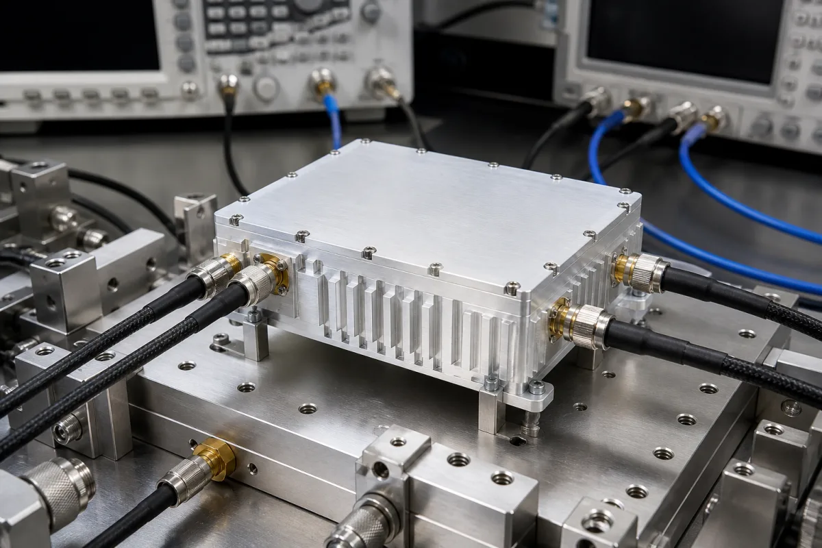
RF Filter/Duplexer in a manufacturing environment
Representative product image. Confirm appearance and specifications with the manufacturer.

Product Specifications

Technical details and manufacturing context for RF Filter/Duplexer

Definition
Within an RF Transceiver Module, the RF Filter/Duplexer is a critical component that manages signal integrity and isolation. It filters incoming and outgoing radio frequency signals to prevent interference, and in duplexer configuration, enables the transceiver to transmit and receive signals simultaneously on different frequencies using a single antenna by providing high isolation between transmit and receive paths. This component is used in the Computer, Electronic and Optical Product Manufacturing industry as a part-level component. The RF Filter/Duplexer operates based on resonant circuits, using inductors, capacitors, and sometimes acoustic wave devices like SAW or BAW, to create frequency-selective passbands and stopbands. A duplexer typically combines transmit and receive filters with a circulator or switch to separate the signals, allowing bidirectional communication over a shared antenna while preventing the powerful transmit signal from overwhelming the sensitive receiver. The component is available with a frequency range of 0.5–6.0 GHz, insertion loss of ≤1.5 dB, return loss of ≥15 dB, stopband attenuation of ≥40 dB, power handling of 10–50 W, impedance of 50 Ω, operating temperature of -40–85 °C, storage temperature of -55–125 °C, dimensions of 20×15×5 mm, weight of 5–15 g, SMA connector type, and IP65 rating per IEC 60529. Materials on file include ceramic substrate, piezoelectric crystal (for SAW/BAW), copper/tungsten electrodes, and epoxy encapsulant. These values are reference ranges and must be verified with the legal manufacturer or supplier for the specific model and application. The listed IP rating is a procurement reference, not a guarantee of compliance. For selection, consider the required frequency bands, insertion loss, return loss, stopband rejection, power handling, impedance, temperature range, mechanical dimensions, connector type, and environmental protection. Verification questions should include confirming the exact frequency response, power handling under peak conditions, and compliance with relevant standards. Maintenance signals include degradation in insertion loss or return loss, which may indicate wear or damage. Failure boundaries include exceeding power handling or temperature limits, which can cause permanent damage.
Working Principle
The RF Filter/Duplexer operates based on resonant circuits, using inductors, capacitors, and sometimes acoustic wave devices like SAW or BAW, to create frequency-selective passbands and stopbands. A duplexer typically combines transmit and receive filters with a circulator or switch to separate the signals, allowing bidirectional communication over a shared antenna while preventing the powerful transmit signal from overwhelming the sensitive receiver.
Common Materials
Ceramic Substrate, Piezoelectric Crystal (for SAW/BAW), Copper/Tungsten Electrodes, Epoxy Encapsulant
Technical Parameters
ParameterTypical rangeNotes & selection driver
Frequency Range0.5–6.0 GHzCovers common communication bands; outside requires custom design.
Insertion Loss≤1.5 dBLower is better for signal integrity.
Return Loss≥15 dBHigher indicates better matching.
Attenuation (Stopband)≥40 dBEnsures adequate rejection of unwanted frequencies.
Power Handling10–50 WAverage power; peak may be higher.
Impedance50 ΩStandard system impedance.
Operating Temperature-40–85 °CExtended range available on request.
Storage Temperature-55–125 °CNon-operating survival range.
Dimensions (L×W×H)20×15×5 mmTypical package; custom sizes available.
Weight5–15 gDepends on package and materials.
Connector TypeSMAOther types (N, BNC) available.
IP RatingIP65Dust-tight and protected against water jets.IEC 60529

Ranges are indicative industry figures for RFQ preparation, not a supplier commitment. Confirm every value and standard with the legal manufacturer before ordering.

Components / BOM
  • Resonator Array
    Creates the frequency-selective response through electromagnetic or acoustic resonance
    Material: Piezoelectric Crystal/Aluminum Nitride
  • Input/Output Couplers
    Transfers RF energy between the external ports and the resonator structure
    Material: Copper/Gold
  • Packaging Part
    Provides mechanical protection, thermal management, and electrical shielding
    Material: Ceramic/Metal Epoxy
  • Circulator or Switch Optional
    Routes transmit and receive paths to one shared antenna — the part that makes it a duplexer rather than a filter.

Applied To / Applications

This component is essential for the following industrial systems and equipment:

Industrial Ecosystem & Supply Chain Structure

Complementary Systems
Downstream Applications
Specialized Tooling

Application Fit & Sizing Matrix

Operational Limits
pressure: Atmospheric to 2 atm (typical), hermetic sealing required
other spec: Frequency range: 100 MHz to 6 GHz, Insertion loss: <2 dB, Return loss: >15 dB, Power handling: 1W to 100W
temperature: -40°C to +85°C (operational), -55°C to +125°C (storage)
Media Compatibility
✓ Cellular base station environments ✓ Satellite communication systems ✓ Military radio equipment
Unsuitable: High-vibration industrial machinery without proper mounting
Sizing Data Required
  • Center frequency (MHz/GHz)
  • Bandwidth requirements (MHz)
  • Isolation between Tx/Rx paths (dB)

Reliability & Engineering Risk Analysis

Failure Mode & Root Cause
Dielectric Breakdown
Cause: Overvoltage conditions, moisture ingress, or contamination causing electrical arcing within the filter components, leading to insulation failure and short circuits.
Mechanical Fatigue of Connectors
Cause: Repeated thermal cycling, vibration, or improper torque during installation causing cracks, loosening, or contact degradation at RF connectors, resulting in signal loss or intermittent connections.
Maintenance Indicators
  • Sudden increase in insertion loss or VSWR (Voltage Standing Wave Ratio) beyond specifications, indicating internal component degradation.
  • Audible arcing or popping noises during operation, suggesting dielectric breakdown or loose internal connections.
Engineering Tips
  • Implement strict torque control and alignment procedures during connector installation to prevent mechanical stress and ensure proper mating surfaces.
  • Maintain environmental controls (e.g., humidity, temperature) and regular cleaning to prevent contamination and moisture ingress, which accelerate dielectric breakdown.

Indicative industry ranges for design and RFQ preparation. Confirm the exact figures and applicable standard with the manufacturer before specifying.

Compliance & Manufacturing Standards

Applicable Standards
ANSI C83.16 - RF connectors and cable assemblies DIN EN 61326-1 - Electrical equipment for measurement, control and laboratory use

Quoted from the published standard.

Manufacturing Precision
  • Center frequency: +/- 0.5% of specified value
  • Insertion loss: +/- 0.3 dB maximum deviation
Quality Inspection
  • VSWR (Voltage Standing Wave Ratio) measurement
  • Temperature cycling test (-40°C to +85°C)

Manufacturers of RF Filter/Duplexer

Manufacturer profiles associated with RF Filter/Duplexer.

Sourcing RF Filter/Duplexer from China?
Tell us your specification and target quantity — we will match it against manufacturer records and come back with the factories that fit.
Request manufacturers We manufacture this

Manufacturer listings support early research and capability understanding. They are not certification, ranking, or transaction guarantees.

Share this page
Technical documentation
Request current drawings, revision history, and a signed specification sheet.
Manufacturing capability
Verify equipment lists, process limits, capacity, and representative production evidence.
Inspection readiness
Confirm test methods, calibrated equipment, sampling plans, and traceable reports.
Supplier transparency
Check the legal entity, factory address, ownership, certifications, and direct contacts.

CNFX does not score or rank suppliers. Buyers must verify all claims and documents with the legal manufacturer before ordering.

Supply Chain Compatible Machinery & Devices

Modular Industrial Edge Computing Device

This modular industrial edge computing device is a ruggedized system designed for deployment in harsh industrial environments to perform real-time data processing, analytics, and control functions at the network edge.

Explore Specs →
Industrial Smart Camera Module

The Industrial Smart Camera Module is a compact, self-contained vision processing unit designed for integration into industrial machinery and production lines.

Explore Specs →
Surface Mount Resistor

Passive electronic component for current limiting and voltage division in circuits

Explore Specs →
Surface Mount Capacitor

A surface mount capacitor is a fundamental electronic component used for energy storage, filtering, coupling, and decoupling in electronic circuits.

Explore Specs →

Frequently Asked Questions

What is the frequency range of this RF Filter/Duplexer?

The reference frequency range is 0.5–6.0 GHz, covering common communication bands. For frequencies outside this range, a custom design is required. Always verify the exact frequency response with the manufacturer for your specific application.

What is the insertion loss and return loss?

The reference insertion loss is ≤1.5 dB, and the return loss is ≥15 dB. Lower insertion loss is better for signal integrity, and higher return loss indicates better matching. These values are typical and must be confirmed for the specific model.

What is the power handling capability?

The reference average power handling is 10–50 W, with peak power possibly higher. Ensure that your application's power levels do not exceed the rated values to avoid damage. Confirm the exact power handling with the supplier.

What is the IP rating and what does it mean?

The reference IP rating is IP65 per IEC 60529, meaning the component is dust-tight and protected against water jets. This rating is a procurement reference and does not guarantee compliance; verify with the manufacturer for your specific unit.

Data Basis

Editorial classification, named public sources where available, and source-reviewed manufacturer records.

Preliminary Technical Classification
This page supports structured research, RFQ preparation, and supplier evaluation. It does not replace buyer-led supplier qualification, standards review, or technical approval.
Buyer enquiry

Request manufacturing insight for RF Filter/Duplexer

Ask for use case, specification boundaries, supplier type, and RFQ preparation information for this product.

Where it goes
Straight to the CNFX editorial desk, and to the manufacturer if this product is linked to a claimed profile. Nothing is broadcast to a supplier list.
Your details stay here
We do not sell or rent enquiry data, and we do not add you to a mailing list. Used only to answer this request.
No commission, no middleman
CNFX is a directory. We take no cut of any order and never negotiate on a supplier's behalf.
What we don't claim
A listing is not an endorsement. Qualify every supplier and verify every figure yourself before ordering.

Your business information is used only to process this request.

Thank you! Your message has been sent. We'll respond within 1–3 business days.
Sorry, we couldn't send your message. Please try again, or email us at [email protected].

Need to Manufacture RF Filter/Duplexer?

Compare manufacturer profiles with relevant product and process capability.

Previous Product
XY Positioning Stage
Last Product
Get QuotesChat