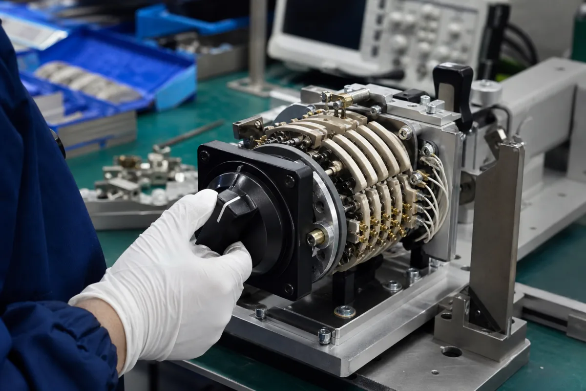
Rotary function selector switch: multi-section detent switches for instruments and control panels, sized by angle of throw, contact type and current class
The multi-section rotary switch that selects a measuring function or circuit by turning a knob · angle of throw against number of positions, shorting and non-shorting contacts, contact resistance from 10 mΩ new to 100 mΩ at low level, and the step from a 2 A circuit selector to a 15 A control switch
Turning the knob of a rotary function switch moves a rotor through a fixed angle to the next detent, and in every section stacked along the shaft a moving contact leaves one set of clips and meets the next. How many positions it has, whether it makes the new contact before breaking the old one, how much current each section can switch, and how low and stable its contact resistance stays decide whether it suits a millivolt measuring circuit or a 600 V control panel.
Multi-section detent rotary switches used as function and circuit selectors on test instruments, meters and control panels: wafer and detent-action switches with stacked sections, shorting or non-shorting contacts and set angles of throw, from low-current circuit selectors to 15 A control and instrument-transfer switches, and the board-mounted selector switches inside handheld multimeters. Knife-blade test switches for protective relays and meters, with current-shorting poles and test plugs, are covered on the Test switch page; rotary encoders that report shaft angle rather than switch circuits, and cam switches for motor control, are outside this page.
CNFX editorial research · Sources checked October 12, 2026 · 4 sources
A 2 A circuit selector or a 15 A, 600 V control switch: two rating classes compared
MIL-DTL-3786G is the US Department of Defense specification for rotary circuit-selector switches for low-power AC or DC switching in electronic and communications equipment, making and breaking a resistive load of 2 A or less unless otherwise specified. Electroswitch's Series 28 and Series 21 detent-action rotary switches sit in a heavier class: [1][2][3]
The Series 21's interrupting current falls with voltage and on DC: 15 A at 120 V AC, 7.5 A at 240 V AC and 4 A at 600 V AC, but 10 A at 24 V DC and only 2 A at 125 V DC; it carries 35 A for 30 or 60 seconds and 140 A for 3 seconds. The Series 28 interrupts 5 A at 120 V AC, 3 A at 240 V AC and 2 A at 600 V AC. Both are UL Recognized and CSA Certified. [3][2]
For low-level measuring circuits, MIL-DTL-3786G tests contact resistance with the contacts loaded at no more than 10 mA resistive and 30 mV open circuit, and specifies rotational life classes from 25,000 cycles at −65 to +85 °C up to 100,000 cycles, with 10,000 cycles no longer for new designs. [1]
State the highest current and voltage each section must switch, AC or DC, and whether any section carries millivolt or milliamp signals where low-level contact resistance applies.
02
Angle of throw sets the positions: 22.5° gives 16, 45° gives 8, and shorting or non-shorting contacts decide the changeover
MIL-DTL-3786G defines the angle of throw as the rotation between consecutive detented positions and lists 7, 11, 13, 15, 18, 22, 26, 30, 36, 45, 60, 72 and 90°. Electroswitch builds Series 28 at 22.5° with 2 to 16 positions and Series 21 at 45° with 2 to 8. [1][2][3]
The specification defines a shorting switch, also called make-before-break, as one where the next contact closes before the first opens, and a non-shorting switch, break-before-make, as one where the first contact fully breaks before the second is made; it requires a positive detent that keeps the rotor from coming to rest between positions, and forbids glass or other fragile materials in the detent. [1] Editorial note: a section that changes current ranges through shunts has to keep the current path closed while it switches, whereas a section that moves between unrelated circuits must never join them, so the contact type belongs in the specification for each section.
Each section is a rotor and stator with stationary clips and a moving rotor contact; the pole terminal (the specification also calls it the collector) connects through the rotor to each position's clip in turn. Terminals take two wires of 0.032 inch nominal diameter, and gold plating on them must be at least 15 microinches. [1]
Give the number of positions, the angle of throw, stops, and for each section the poles and whether contacts are shorting or non-shorting.
03
Inside a handheld multimeter: contact fingers on the circuit board instead of stacked wafers
Fluke's patent US 8,093,516 B2 describes the selector of a digital multimeter that offers ten functions at ten knob stop positions. There are no wafers: switch members carrying contact pairs press on conductive pads printed on the main circuit board and connect pairs of pads for the selected function. [4]
Two switch members sit on opposite sides of the circuit board, joined by a shaft in a fixed angular orientation; the first has at least four contact pairs and the second at least three, plus a non-functional sweeper that balances the spring force so the member does not tilt. Each contact pair is a pair of spring fingers in nickel-plated beryllium copper. A detent disc inside the case turns with the knob, and spring arms moulded on it push protuberances into the valleys between teeth so the knob stays where it is set. [4]
Editorial note: this board-pad construction saves depth and parts in a handheld instrument, while stacked-section switches of the kind in the two tables above carry their own contact clips and insulation ratings; when a function switch is specified for a bench instrument or panel, ask which construction is offered and test contact resistance at the instrument's signal level. [4][1]
For an instrument selector, state the number of functions, the board layout constraints, and the contact material and plating expected.
04
What to send when specifying a rotary function switch
Paste it into your enquiry below or into an email to a maker, then replace every bracket.
Use: [instrument function selector / meter transfer / control panel]
Positions: [number; angle of throw; stops; spring return]
Sections: [number; poles per section; shorting or non-shorting per section]
Electrical: [current and voltage per section; AC/DC; low-level signals]
Insulation: [dielectric test voltage; insulation resistance; section material]
Life and environment: [rotational cycles; temperature range; sealing]
Mounting: [shaft and knob; panel hole; terminals]
Explore company information and manufacturing capabilities, then discuss the scope of your project with a relevant supplier.
Share this page
Compiled and source-reviewed by the CNFX editorial team.
Each manufacturer above links to the page on that company's own website where the product is listed, with the date we checked it. How we source and review
· Page last updated 13 October 2026
Buyer questions
What contact resistance should a rotary selector switch have?
MIL-DTL-3786G sets 10 mΩ initially, 20 mΩ after the life test and 100 mΩ for low-level circuits; Electroswitch lists 10 mΩ for its Series 21 and 28. [1][3][2]
How many positions does a rotary switch have?
It follows the angle of throw: Electroswitch's 22.5° Series 28 offers 2–16 positions and its 45° Series 21 offers 2–8. [2][3]
What is a shorting rotary switch?
A make-before-break switch: the next contact closes before the first opens. A non-shorting switch breaks the first contact fully before making the next. [1]
How is the function switch built in a handheld multimeter?
In Fluke's patent, nickel-plated beryllium-copper contact fingers on two switch members press on pads on the main circuit board, with a detent disc holding each of ten positions. [4]
Sources and what still needs a direct check
Sources checked 2026-10-12. Low-current selector requirements come from the US Department of Defense specification MIL-DTL-3786G; heavier detent switch ratings from Electroswitch's Series 21 and Series 28 specification pages; the multimeter construction from a Fluke patent.