Signal Processing Board
View system integration details
This page explains how Signal Amplifier Circuit is classified within Computer, Electronic and Optical Product Manufacturing. Technical values and manufacturer relationships are research references; confirm the current specification and supplier evidence for each order.
Electronic circuit that increases the amplitude of input signals while maintaining signal integrity
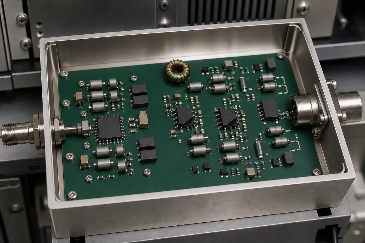
Technical details and manufacturing context for Signal Amplifier Circuit
| Parameter | Typical range | Notes & selection driver |
|---|---|---|
| Supply Voltage | 9–36 V DC | Operating range; outside may cause malfunction |
| Gain | 20–60 dB | Adjustable; higher gain increases noise |
| Bandwidth | 0.1–100 MHz | At -3 dB; beyond this gain rolls off |
| Input Impedance | 50–75 Ω | Match source impedance for minimal reflection |
| Output Impedance | 50–75 Ω | Match load impedance for maximum power transfer |
| Noise Figure | 1.5–3.0 dB | Lower is better for weak signals |
| Total Harmonic Distortion | ≤0.1 % | At rated output; higher distortion degrades signal |
| Operating Temperature | -40–85 °C | Beyond this range performance may degrade |
| Humidity | 5–95 % RH | Non-condensing; condensation may cause short circuits |
| Ingress Protection | IP54–IP65 | Protects against dust and water jetsIEC 60529 |
| Weight | 0.5–2.0 kg | Depends on enclosure and connectors |
Ranges are indicative industry figures for RFQ preparation, not a supplier commitment. Confirm every value and standard with the legal manufacturer before ordering.
| voltage: | ±15V maximum supply |
| humidity: | 0-85% non-condensing |
| frequency: | DC to 100MHz |
| temperature: | -40°C to +85°C |
| input signal range: | ±10V maximum |
Indicative industry ranges for design and RFQ preparation. Confirm the exact figures and applicable standard with the manufacturer before specifying.
Quoted from the published standard.
A practical evidence checklist for RFQ preparation and supplier evaluation.
Compare the published product scope and source details, then include your specifications and quantity in an enquiry.
Manufacturer profiles associated with Signal Amplifier Circuit.
Explore company information and manufacturing capabilities, then discuss the scope of your project with a relevant supplier.
Ask for use case, specification boundaries, supplier type, and RFQ preparation information for this product.
The supply voltage range is 9–36 V DC. Operating outside this range may cause malfunction. Always verify the exact requirement for your specific model.
Gain is adjustable from 20–60 dB. Higher gain increases the output amplitude but also increases noise. The optimal setting depends on the input signal level and the required output.
Input impedance should match the source impedance (50–75 Ω) to minimize signal reflection, and output impedance should match the load impedance for maximum power transfer. Mismatches can cause signal degradation.
The operating temperature range is -40 to 85 °C, and humidity should be 5–95% RH non-condensing. Condensation can cause short circuits. The ingress protection rating (IP54–IP65) indicates resistance to dust and water jets, but actual protection depends on the enclosure.
This component is essential for the following industrial systems and equipment:
Editorial classification, named public sources where available, and source-reviewed manufacturer records.
Compare manufacturer profiles with relevant product and process capability.