Bed-of-nails and functional test fixtures · Probe pitch and pad size, tolerance stack, probe travel and spring force
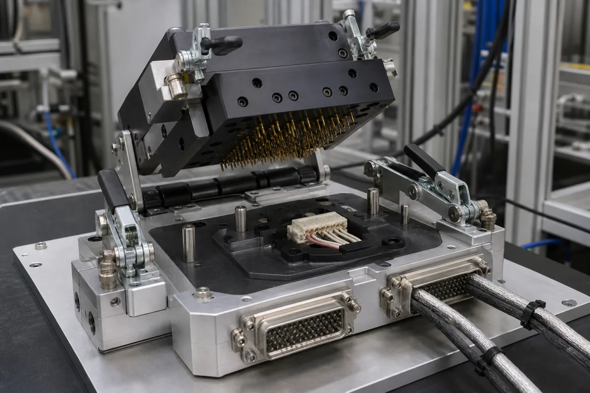
A test fixture holds a printed circuit board assembly or module in a defined position and presses spring-loaded probes onto its test pads and connectors, so an in-circuit or functional tester can measure it; the clamshell fixture pictured closes a probe plate onto the part with toggle clamps. Ask three things first: whether the board's test pads, pitch and tooling holes suit standard probes, whether fixture and board tolerances leave enough margin for reliable contact, and which probe travel and spring force the fixture uses.
Bed-of-nails in-circuit test (ICT) and functional test (FCT) fixtures for PCB assemblies and electronic modules, with their spring probes. Test sockets for bare chips, battery cell test holders, and grips for mechanical testing machines are outside this page.
CNFX editorial research · Sources checked October 12, 2026 · 4 sources
JJS Manufacturing's in-circuit testability guidelines recommend keeping test points at least 0.100 in apart so standard 100 mil probes can be used; smaller probes reach 0.050 in but bring more contact problems, lower long-term reliability and higher cost. Test pads should preferably be 0.05 in in diameter, with a minimum of 0.035 in on the bottom side and 0.040 in for top-side probing, kept at least 0.125 in from the board edge and 0.100 in from components. [1]
The same paper lists typical fixture and board tolerances — fixture drilling ±0.002 in, probe perpendicularity ±0.003 in, tip run-out ±0.002 in, tooling pin accuracy ±0.003 in and board tolerances — that stack to 0.032 in against a 0.035 in pad, leaving only ±0.0015 in of margin, which is why it says “It is most critical to control and monitor the PCB artwork tolerance”. It asks for two non-plated tooling holes of at least 0.125 in in diagonally opposite corners, a minimum board thickness of 0.062 in and solder-side components no taller than 0.100 in. [1]
Editorial calculation: in metric terms the 0.035 in minimum pad is about 0.89 mm, the preferred 0.05 in pad about 1.27 mm, and the 0.0015 in margin about 0.04 mm.
Give the supplier the board CAD data with test pad coordinates, bill of materials, schematics, populated and bare boards, the target tester and interface, test types (ICT, FCT or both), actuation (vacuum, pneumatic or manual), cycle time and expected volume.
02
Choose probe size, travel and spring force
PTR's datasheet for its 1025/E series, an international-standard 100 mil ICT probe on a 2.54 mm centre, gives full travel of 6.40 mm and working travel of 4.30 mm, pre-loaded spring forces from 0.20 to 1.40 N and forces at working travel from 0.60 to 4.00 N, a current rating of 5.0 to 8.0 A and typical continuity resistance of 20 mΩ or less. [2]
Editorial calculation: 500 probes at 1.50 N each at working travel press the board with about 750 N, or 1,000 N at 2.00 N per probe. JJS Manufacturing says “Pusher rods are typically 2mm diameter, and one is required for approximately every 2in2 of PCB”, especially where probes are dense; a 160 × 100 mm board (about 24.8 in²) would need around 12. [2][1]
A second probe maker's data show how high-force ICT probes differ. Promax (Dongguan) lists its PT137A200-3340A high-force ICT probe at 33.40 ± 0.10 mm overall length, Ø0.90 mm plunger, 6.40 mm full stroke and 4.30 mm working stroke, 200 gf ±20% spring force, below 20 mΩ contact resistance, 3.0 A continuous and 10 A instantaneous current, and durability of at least 3,000 cycles. [3]
Editorial calculation: 200 gf is about 1.96 N per probe, within the range of PTR's heavier springs, so 500 such probes load the board with roughly 980 N. The two makers' 6.40 mm full and 4.30 mm working travel match, but durability is stated as at least 3,000 cycles on the Promax sheet, so ask each supplier for life-test data on the probe and tip style you will use. [3][2]
JJS Manufacturing notes that “fixtures for ICT are normally actuated by vacuum”, with mechanical and pneumatic options also available. Where a fixture serves both ICT and functional test, the ICT probes must be withdrawn during the functional cycle, using a shuttle plate with standard and long-throw probes, a two-stroke pneumatic press, or discrete pneumatic probes; long-throw probes are reliable in 0.100 in format, and it recommends at least 0.075 in probes and two test points per functional net. It warns against probing SMT component legs, which can make a dry joint pass. [1]
03
Size the fixture's interface to the tester: nodes, nests and cycle time
A 2026 HardwareX paper from Universidad Autónoma de Ciudad Juárez describes an open-hardware ICT/FCT test board built for a fixture with independent nests: each board connects to its device under test through an 88-pin gold-finger edge connector that routes signals to pogo pins on a custom receiver fixture plate, and the mechanical fixture is indexed to a multi-cavity pallet so one board tests each nest in parallel. [4]
The authors position the board for prototyping and low-volume production, not as a substitute for high-volume industrial ICT/FCT systems, and state that ESD events, device fault injection and incorrect fixture connections were not tested experimentally. [4]
Editorial calculation: a fixture with 500 probed nodes needs 32 boards of 16 nodes (500 ÷ 16 = 31.25) if each node needs its own channel, against one 2-module system of 2,592 nodes. Give the fixture builder the tester model, its node count and connector, how many nests run in parallel, and the probe count per nest, so the receiver plate wiring matches the tester. [4]
Suppliers linked to this page list test fixtures or the probes used in them; each card links to the page reviewed.
Listings include PCBA, FCT, ICT, BGA, display and pneumatic test fixtures, fixtures built by electronics manufacturing service providers for the boards they assemble, memory module test fixtures, power supply test fixtures and high-current test probes. Ask each supplier for the probe make and series, the tolerance stack it designs to, and the probe replacement interval.
05
Trace the fixture parts
This is a functional reference built from the sources cited; it is not one maker's specification.
Fill the specification fields with values for your board
A test fixture quotation needs values for your board and tester. The table explains each field, gives published values where a reviewed source states them, and says what to obtain from the supplier.
Field
What it means and published values
Ask the supplier for
Clamping Force (N)
Must exceed total probe force; e.g. 500 × 1.5 N = 750 N, or ~980 N at 200 gf (editorial). [2][3]
Explore company information and manufacturing capabilities, then discuss the scope of your project with a relevant supplier.
Share this page
Compiled and source-reviewed by the CNFX editorial team.
Published product pages show what a company offers, not tested performance. Confirm the legal seller, factory and scope for your order. How we source and review
· Page last updated 13 October 2026
Buyer questions
How far apart should test points be?
JJS Manufacturing recommends at least 0.100 in so standard 100 mil probes can be used; smaller probes reach 0.050 in at higher cost and lower reliability. [1]
How large should a test pad be?
JJS Manufacturing prefers 0.05 in, with a minimum of 0.035 in on the bottom side and 0.040 in for top-side probing. [1]
How far should an ICT probe be compressed?
PTR's 100 mil 1025/E probe lists 4.30 mm working travel out of 6.40 mm full travel. [2]
How much force do high-force ICT probes put on a board?
One maker's high-force probe is rated 200 gf (about 1.96 N), so 500 probes push with roughly 980 N, which the fixture's hold-down must exceed. [3]
How does a test fixture connect to the tester?
In one open-hardware design from Universidad Autónoma de Ciudad Juárez, each 16-node test board plugs into an 88-pin gold-finger edge connector wired to pogo pins on the fixture's receiver plate, one board per nest, with ICT/FCT cycles of about 10–50 ms per device. [4]
Sources and what still needs a direct check
Sources checked 2026-10-12. JJS Manufacturing is an electronics manufacturing services company; its guidelines reflect its fixture practice. PTR is a test probe maker; values are for its 1025/E series. A Universidad Autónoma de Ciudad Juárez HardwareX paper describes an open-hardware ICT/FCT tester and its fixture interface.