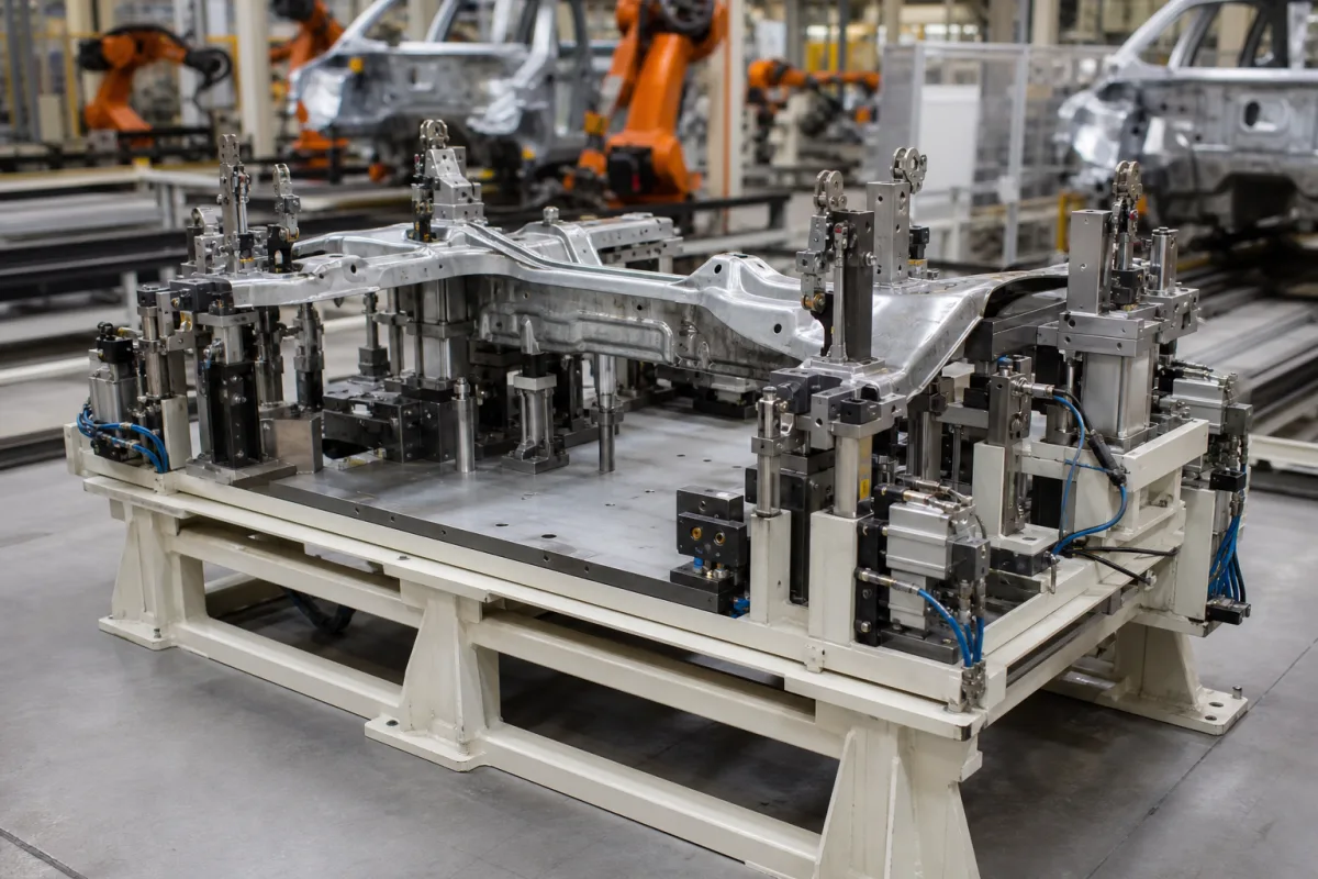
The fixture in the illustration holds a pressed-steel body sub-assembly on a row of supports and pneumatic clamp towers, with locating pins rising through holes in the panel, on a welded base frame in a body shop with robots behind. A rigid block would need only three supports under it; a thin pressed panel sags and twists between them, so this kind of fixture is laid out by different rules and checked in a different way.
Covers assembly fixtures for compliant sheet-metal parts in vehicle body-in-white sub-assembly: the N-2-1 locating principle, 4-way pin-hole and 2-way pin-slot locators, out-of-plane supports and clamps, pneumatic power clamp holding torque and position sensing, locator layout against part deformation, and diagnosing fixture faults from measurement data. Weld fixture bases, bore systems, datums and distortion control for welded assemblies of any kind are on Welding fixtures; manual toggle clamps are on Toggle-clamp clamping fixture for welding. Electronics (PCBA) assembly fixtures and transformer radiator assembly fixtures are outside this page.
CNFX editorial research · Sources checked October 12, 2026 · 4 sources
N-2-1: more than three supports for a flexible part
Camelio and Hu (University of Michigan, Journal of Manufacturing Science and Engineering) set out the locating rules for sheet-metal fixtures.
Fixture elements divide into locators, which set the datum frame and restrain the part kinematically, and clamps, which hold it against outside forces during the process. A rigid body is located by 3-2-1: three locators in the primary plane, two in the secondary and one in the tertiary. For compliant sheet metal, the authors cite Cai et al.: an N-2-1 principle fits better and is used across industry, because part flexibility means more than three locators are needed in the primary plane.
Their worked case is a 4-2-1 scheme: four clamps hold the part in the out-of-plane direction, while a 4-way pin in a round hole and a 2-way pin in a slot locate it in-plane. The 4-way pin fixes the two in-plane translations; the 2-way pin in the slot then stops rotation about the first pin without over-constraining the panel along the line between them.
Wang et al. (Computational Intelligence and Neuroscience, 2016) note that the fixture constrains excessive sheet-metal deformation at machining, assembly and measuring stages, and that there is no direct, explicit expression linking locator layout to the resulting deformation; they train a neural network on finite-element results to predict it. In practice the N supports are placed by simulation, not by rule of thumb.
Element
Restrains
In the illustration
4-way pin in a round hole
Both in-plane translations
Pins rising through panel holes
2-way pin in a slot
Rotation in the plane, about the 4-way pin
Second pin at the far end of the part
N supports with clamps (N > 3)
Out-of-plane position and sag
Support blocks under pneumatic clamp arms
The roles of the 4-way and 2-way pins are an editorial explanation of the paper's 4-2-1 description. Ask for the locating scheme drawing with each pin's type, size and hole or slot, and the simulation used to place the supports.
02
Clamp holding torque and force at the tip
Pneumatic power clamps are specified by holding torque, which depends on where along the arm the clamp pad sits.
Force at the tip = holding torque ÷ arm length; moving the pad further out lowers it in proportion (Editorial calculation from DESTACO's listed torque and arm length). Holding torque is the load the clamp resists once locked, not the force it applies while closing.
DESTACO's product pages list accessory part numbers for each clamp; a fixture that confirms every clamp is closed before the robot starts welding needs open and closed sensing specified per clamp (editorial note).
DESTACO model
Cylinder bore
Arm
Arm length
Max holding torque
Force at that arm length
860
2 in
Vertical
5.44 in (138 mm)
280 ft·lb (≈380 N·m)
≈618 lbf (≈2.75 kN)
891
2.5 in
Horizontal
5.06 in (129 mm)
960 ft·lb (≈1,302 N·m)
≈2,277 lbf (≈10.1 kN)
Ask for clamping (closing) torque at the shop air pressure as well as holding torque, the pad position on each arm, and the sensor type for open and closed confirmation.
03
Fixture faults and how they show up
Camelio and Hu cite Ceglarek and Shi: during a new vehicle launch, fixture faults account for around 70% of all dimensional faults. With optical CMMs producing large amounts of dimensional data on the line, fixture faults can be diagnosed from measured deviation patterns instead of by inspecting every element.
They distinguish fault types. A locating element that is worn or displaced but still present forces the part to a wrong position, which the measurement data reveal. A clamp that is loose or missing may not show up at all unless gravity or another force acts in the direction it was meant to restrain. Their method uses designated patterns per fault, and in the 4-2-1 example nine out-of-plane measuring points were used.
Fault
Effect on part (Camelio and Hu)
Detectable from measurement?
Locator worn or displaced, still present
Part forced to a non-nominal position
Yes
Clamp missing or loose
Depends on whether a force acts in its direction
Only if gravity or another force moves the part
Two or more faults at once
Combined deviation
Depends on how the fault patterns relate
Ask how the fixture is certified (CMM check of locator positions), the re-certification interval, and which measurement points on the part map to each locator and clamp.
04
What to give a body fixture builder
Paste it into your enquiry below or into an email to a maker, then replace every bracket.
Send the part and sub-assembly CAD with the locating scheme (RPS points if defined), material and thickness, the joining process and robot access, cycle time and air pressure. Ask for the N-2-1 layout with pin types, sizes and slot directions, support and clamp positions with the simulation behind them, clamp models with clamping and holding torque at the pad position, open and closed sensing per clamp, the certification method and tolerances for locators, and spare pins and pads.
1 company lists this product among what they make. Company figures are quoted from each
company's own website; every card states where the relationship came from.
Anchuang's welding-fixture pages list a car battery box tray welding fixture alongside robot welding cells, positioners and automated lines; ask for the locating scheme and clamp specification for your part.
Explore company information and manufacturing capabilities, then discuss the scope of your project with a relevant supplier.
Share this page
Compiled and source-reviewed by the CNFX editorial team.
Each manufacturer above links to the page on that company's own website where the product is listed, with the date we checked it. How we source and review
· Page last updated 13 October 2026
Buyer questions
Why do sheet-metal fixtures use more than three supports?
Because the part is flexible: Camelio and Hu describe the N-2-1 principle, with more than three locators in the primary plane, as more adequate than 3-2-1 for compliant sheet metal; Wang et al. place the supports by predicting deformation from finite-element results. [1][2]
What are 4-way and 2-way pins?
In Camelio and Hu's 4-2-1 example a 4-way pin in a hole and a 2-way pin in a slot locate the part in-plane, while four clamps hold it out-of-plane. [1]
How much force does a pneumatic power clamp hold at the arm tip?
Divide holding torque by arm length: DESTACO's 860 (280 ft·lb, 5.44 in arm) gives about 618 lbf, the 891 (960 ft·lb, 5.06 in) about 2,277 lbf (Editorial calculation). [3][4]
How much do fixtures contribute to body dimensional problems?
Camelio and Hu cite Ceglarek and Shi: around 70% of dimensional faults during a new vehicle launch come from fixtures. [1]
Sources and what still needs a direct check
Sources checked 2026-10-12. A peer-reviewed sheet-metal fixture study, a peer-reviewed locator-layout paper and a clamp maker's product data.