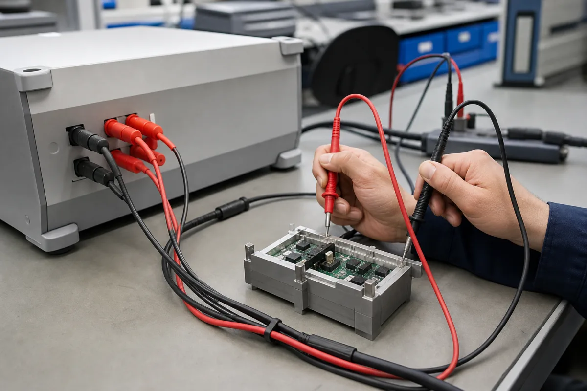
Test leads that connect a multimeter or electrical tester to the circuit under test · Measurement category and voltage rating, current rating, exposed probe tip length, insulation material, connector and accessory tips, lead length and environmental rating
Test leads carry the measurement from the circuit under test to the meter, and on live electrical systems they are the part the user holds. Their ratings must match the meter and the circuit. Ask three things first: in which measurement category and at what voltage the leads will be used, how much current they must carry, and which tips and plugs the job and the instrument need.
Test lead sets with probes, plugs and accessory tips for handheld digital multimeters, clamp meters and similar electrical testers. Spring probes for circuit-board fixtures (see test fixture), oscilloscope probes and high-voltage test cables for withstand testers are outside this page.
CNFX editorial research · Sources checked October 12, 2026 · 4 sources
Match the measurement category, voltage and current ratings
Fluke's TL175 TwistGuard test leads are rated CAT II 1000 V, CAT III 1000 V and CAT IV 600 V, 10 A maximum, at pollution degree 2, and are stated to conform to EN 61010-031. The adjustable tip shroud shows the category rating that applies to the tip exposure in use. [1]
Amprobe's TL36A test lead set is rated CAT IV 600 V and CAT III 1000 V. [2]
Editorial note: in both examples the CAT IV voltage rating is lower than the CAT III rating, so check the rating for the category of the circuit you will measure, not only the highest voltage printed on the lead.
Give the supplier the instrument model and its input jacks, the measurement categories and voltages of the circuits to be measured, the maximum current, the probe tips and clips needed, lead length, insulation material, operating temperature range and the safety standard the set must conform to.
02
Choose probe tips, insulation, plugs and length
The TL175 lets the user twist the lead to change the exposed probe tip length from 19 mm to 4 mm. Its silicone insulation has a two-colour wear indicator: if the inner white layer shows through the outer black layer, the leads must be replaced. It uses universal input plugs for instruments that accept standard 4 mm shrouded banana plugs, its strain relief is tested to 30,000+ bends without failure, and its environmental ratings are −20°C to 55°C at up to 2000 m altitude; a TL175E version includes removable 4 mm lantern tips. [1]
The TL36A set has two vinyl lead wires, two threaded probe tips and two threaded alligator clips that screw onto the probe tips; the leads are 48 inches long with the clips attached, and the 2.67-inch clips have a 0.30-inch jaw opening with teeth that grip the conductor for a hands-free connection. [2]
Editorial calculation: 48 inches is about 1.22 m (48 × 25.4 mm = 1,219 mm), and a 0.30-inch jaw opening is about 7.6 mm. [2]
HIOKI's L9300 leads take a different route to tip length: the safety cap is built into the probe, not a separate cover. In the rear position it exposes a longer, slender tip for narrow terminals or PCB test points; for CAT III 1000 V and CAT IV 600 V work it slides forward to cut the exposed contact length, and it locks in each position. The set has angled 4 mm safety banana plugs and finger guards, is rated CAT II 1000 V, CAT III 1000 V and CAT IV 600 V and up to 10 A, is 95 cm long, and is listed at 1,110 mm and 0.075 kg packaged. [4]
Accessory tips carry their own, lower ratings. HIOKI lists the L4934 small alligator clips that fit the L9300 at 3 A maximum, CAT II 600 V and CAT III 300 V for conductors 2 to 4 mm in diameter, and the L4933 extra-thin contact pins at 3 A maximum and 60 V DC / 30 V AC. Editorial calculation: fitting the L4934 clips drops the usable CAT III rating from 1000 V to 300 V and the current from 10 A to 3 A, so the rating that applies is the lowest of lead, accessory and meter. [4]
03
Check leads against the HSE GS38 guidance
The UK Health and Safety Executive's guidance note GS38 (fourth edition, 2015), Electrical test equipment for use on low voltage electrical systems, says test probes, clips and leads should conform to BS EN 61010-031 (or BS EN 61243-3 for two-pole voltage detectors), be marked with their rated category CAT II, III or IV and the maker's name or mark, and have finger barriers or a shape that guards against hand contact with the conductors under test. [3]
GS38 lists incidents linked to inadequately insulated or damaged leads, removed insulation, leads falling off meter terminals, long intertwined leads, leads severed by a closing cabinet door, and use beyond the leads' CAT rating, for example CAT II equipment on a CAT III installation. It describes CAT IV as the source of the installation, CAT III as the building installation and CAT II as circuits connected to it such as appliances. [3]
Editorial calculation: a 2 Ω fuse resistance in a lead pair is a 200% error on a 1 Ω continuity reading unless the meter is zeroed with the leads connected.
GS38 point
Guidance
Exposed metal tip
Not exceeding 4 mm across any surface; 2 mm or less, or spring-loaded retractable screened probes, strongly recommended where practicable
Fusing with a multimeter
High-breaking-capacity (HBC/HRC) fuse, rated up to 500 mA in GS38's guidance; 10 A cited for loop impedance or RCD testers; or a current-limiting resistor and fuse
Fuse resistance
Low-current (500 mA) fuses can add up to 2 Ω to the lead; glass fuses are not suitable
Lead insulation and sheath
Adequately insulated for the environment and sheathed against mechanical damage
Colour
Leads coloured so one can be told from the other
Length
Long enough for the purpose but not unwieldy
Exposed conductors
None other than the probe tips, including if a lead becomes detached
State the highest measurement category and voltage of the circuits you test, whether fused leads are required, and the maximum exposed tip length, and ask for the lead set's EN 61010-031 rating and fuse type.
04
Probe tip, insulated wire, strain relief, banana plug and clips
Each part has its own limit: the wire's insulation carries the wear indicator, the plug has to fit the meter's jacks, and HIOKI's add-on clips and pins are rated below the lead they fit. [1][4]
Hands-free or fine-pitch contact; rated separately, e.g. 3 A, CAT III 300 V. [4]
Rating of each accessory.
05
Category voltage, current, tip exposure, fusing and plug for a lead set order
Conductor cross-section, contact resistance, insulation resistance, ingress protection and set weight have no published value in the sources reviewed, so the supplier has to state them; the last row carries the GS38 limits of 4 mm exposed tip and a fuse of up to 500 mA. [3]
Field
What it means and published values
Ask the supplier for
Rated Voltage
By category, e.g. CAT III 1000 V, CAT IV 600 V. [1][2]
1 company lists this product among what they make. Company figures are quoted from each
company's own website; every card states where the relationship came from.
MEWOI Electronics Co., Ltd
Manufacturing site to be confirmed for the order
Lists special test leads and accessories alongside its earth resistance, insulation and clamp testers.
Explore company information and manufacturing capabilities, then discuss the scope of your project with a relevant supplier.
Share this page
Compiled and source-reviewed by the CNFX editorial team.
Each manufacturer above links to the page on that company's own website where the product is listed, with the date we checked it. How we source and review
· Page last updated 13 October 2026
Buyer questions
What CAT rating do multimeter test leads need?
A rating for the category and voltage of the circuit measured; one set is rated CAT II 1000 V, CAT III 1000 V and CAT IV 600 V. [1]
Why do some probes limit exposed tip length?
One design adjusts exposed metal from 19 mm to 4 mm and shows the category rating that applies to the tip exposure in use. [1]
When should test leads be replaced?
One silicone lead has a wear indicator: if the inner white insulation shows through the black outer layer, the leads must be replaced. [1]
How much bare metal should a test probe tip have?
HSE guidance GS38 says no more than 4 mm across any surface, and strongly recommends 2 mm or less, or spring-loaded retractable screened probes, where practicable. [3]
Do alligator clips change a test lead's rating?
Yes: HIOKI rates its L9300 leads CAT III 1000 V and 10 A, but the L4934 clips that fit them are rated CAT III 300 V, CAT II 600 V and 3 A. [4]
Sources and what still needs a direct check
Sources checked 2026-10-12. The Fluke, Amprobe and HIOKI sources are makers' product pages for specific test lead sets, cited as examples of the parameters a test lead specification covers, not endorsements; HSE guidance note GS38 sets out UK safety guidance.