Editorial Technical Reference

Transmitter Coil Assembly

This page explains how Transmitter Coil Assembly is classified within Computer, Electronic and Optical Product Manufacturing. Technical values and manufacturer relationships are research references; confirm the current specification and supplier evidence for each order.

Technical Definition & Core Assembly

An assembly containing the primary electromagnetic coil responsible for generating and transmitting signals or power in an industrial system.
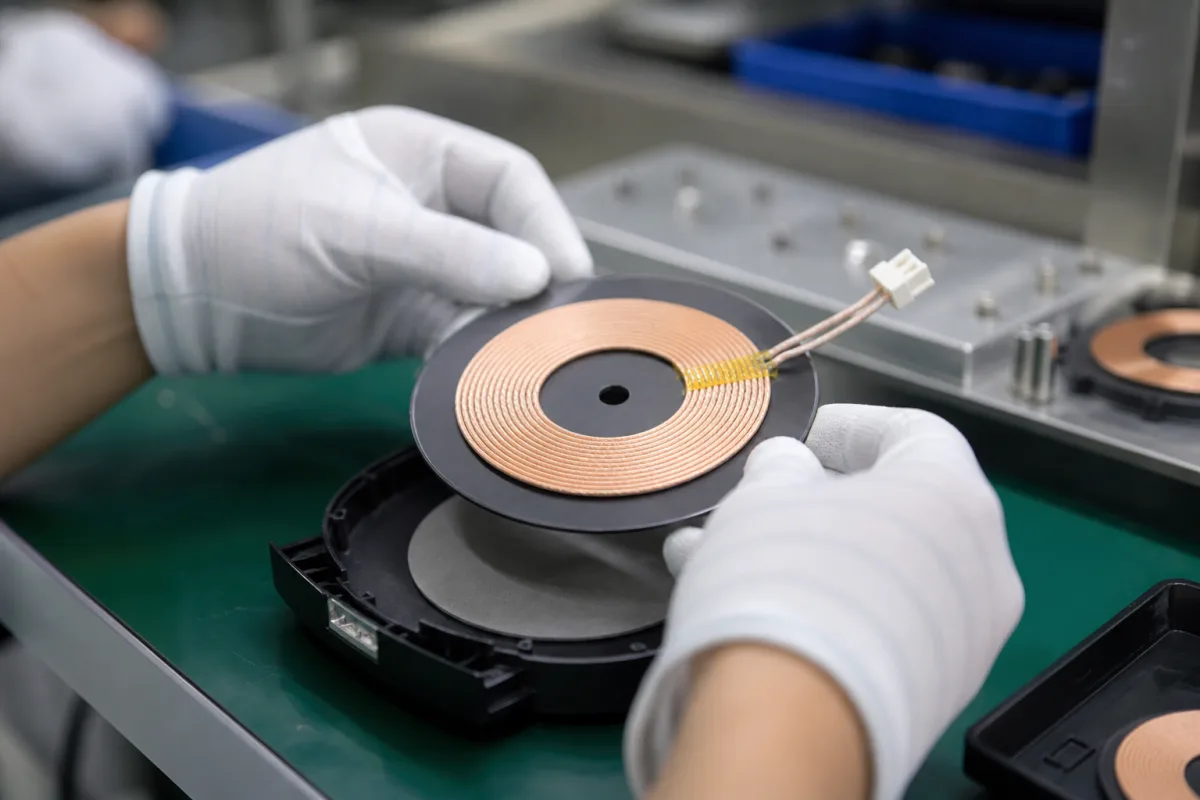
Transmitter Coil Assembly in a manufacturing environment
Representative product image. Confirm appearance and specifications with the manufacturer.

Product Specifications

Technical details and manufacturing context for Transmitter Coil Assembly

Definition
The Transmitter Coil Assembly is a critical electromagnetic component within an Industrial System that generates oscillating magnetic fields or transmits electrical signals through inductive coupling. It serves as the active transmitting element in systems requiring wireless power transfer, proximity sensing, data communication, or inductive heating by converting electrical energy into controlled electromagnetic radiation. The assembly typically consists of a wound copper wire around a ferrite core, with the coil geometry and winding pattern determining the field characteristics, efficiency, and operating frequency range. It is designed for use in computer, electronic, and optical product manufacturing, where it may be integrated into larger systems for energy transfer or signal transmission. The assembly operates within specified electrical parameters, including a rated power of 50–500 W, an operating voltage of 12–48 V DC, and a current consumption of 1–10 A at rated power. Its inductance ranges from 10–100 mH at 1 kHz, and its DC resistance is 0.5–5 Ω. The insulation resistance is at least 100 MΩ at 500 V DC, and the dielectric strength is 1500 V AC for 1 minute, both tested per IEC 60243. The operating temperature range is -40 to 85 °C, with storage from -40 to 105 °C. The assembly is rated IP54–IP65 for dust and water resistance per IEC 60529. The coil wire is enameled copper (Cu) per ASTM B3, and the core is high-permeability ferrite. The weight varies from 0.5 to 2.5 kg depending on size. These values are reference ranges and must be confirmed for the specific model and application. The assembly is a component, not a standalone product, and its performance depends on the system design and operating conditions. For procurement, verify model-specific values and standards with the legal manufacturer or supplier.
Working Principle
When electrical current flows through the wound conductor of the coil assembly, it generates a time-varying magnetic field according to Ampère's law and Faraday's law of induction. This electromagnetic field propagates through space or couples with nearby receiver coils, enabling energy transfer, signal transmission, or inductive effects without physical contact. The assembly's physical construction (coil geometry, winding pattern, core material) determines the field characteristics, efficiency, and operating frequency range.
Common Materials
Copper wire, Ferrite core
Technical Parameters
ParameterTypical rangeNotes & selection driver
Rated Power50–500 WDepends on application requirements
Operating Voltage12–48 V DCTypical for industrial systems
Current Consumption1–10 AAt rated power
Inductance10–100 mHAt 1 kHz
Resistance0.5–5 ΩDC resistance
Insulation Resistance≥100 At 500 V DCIEC 60243
Dielectric Strength1500 V ACFor 1 minuteIEC 60243
Operating Temperature-40–85 °CExtended range available
Storage Temperature-40–105 °CNon-operating
IP RatingIP54–IP65Dust and water resistantIEC 60529
Coil Wire MaterialCuCopper, enameledASTM B3
Core MaterialFerriteHigh permeability
Weight0.5–2.5 kgDepends on size

Ranges are indicative industry figures for RFQ preparation, not a supplier commitment. Confirm every value and standard with the legal manufacturer before ordering.

Components / BOM
  • Coil Winding Part
    Conductive path that carries current to generate electromagnetic fields
    Material: Insulated copper wire
  • Magnetic Core Optional Part
    Concentrates and directs magnetic flux to improve efficiency and field strength
    Material: Ferrite or laminated steel
  • Bobbin/Form Part
    Structural support for winding the coil and providing electrical insulation
    Material: Thermoplastic or ceramic

Industry Taxonomies & Aliases

Commonly used trade names and technical identifiers for Transmitter Coil Assembly.

Applied To / Applications

This component is essential for the following industrial systems and equipment:

Industrial Ecosystem & Supply Chain Structure

Complementary Systems
Downstream Applications
Specialized Tooling

Application Fit & Sizing Matrix

Operational Limits
pressure: 0 to 100 bar
other spec: Max slurry concentration: 30% solids by weight
temperature: -40°C to 150°C
Media Compatibility
✓ Water-based fluids ✓ Non-corrosive gases ✓ Light hydrocarbon liquids
Unsuitable: Highly corrosive acidic environments (e.g., concentrated sulfuric acid)
Sizing Data Required
  • Required power output (kW)
  • Operating frequency range (Hz)
  • Coil diameter constraints (mm)

Reliability & Engineering Risk Analysis

Failure Mode & Root Cause
Coil insulation breakdown
Cause: Thermal degradation from overheating due to excessive current, poor ventilation, or ambient temperature extremes, leading to insulation material breakdown and short circuits.
Mechanical fatigue of coil windings
Cause: Vibration-induced stress from equipment operation or external sources, causing wire fatigue, loosening, or breakage over time, compromising signal integrity.
Maintenance Indicators
  • Intermittent or erratic signal output, indicating potential coil winding damage or connection issues.
  • Audible humming or buzzing from the assembly, suggesting loose windings, insulation failure, or magnetic core problems.
Engineering Tips
  • Implement vibration monitoring and isolation measures, such as mounting dampers or ensuring secure fastening, to reduce mechanical stress on coil windings.
  • Maintain optimal thermal conditions through proper ventilation, ambient temperature control, and regular inspection of electrical connections to prevent overheating and insulation degradation.

Indicative industry ranges for design and RFQ preparation. Confirm the exact figures and applicable standard with the manufacturer before specifying.

Compliance & Manufacturing Standards

Applicable Standards
ANSI/ISA-67.14.01-2000 Transmitter Performance Standards DIN EN 60770-1:2011 Transmitter Requirements for Industrial Process Control

Quoted from the published standard.

Manufacturing Precision
  • Coil Winding Diameter: +/-0.05mm
  • Mounting Surface Flatness: 0.08mm
Quality Inspection
  • Electrical Insulation Resistance Test
  • Dimensional Verification via CMM (Coordinate Measuring Machine)

Manufacturers of Transmitter Coil Assembly

Manufacturer profiles associated with Transmitter Coil Assembly.

Sourcing Transmitter Coil Assembly from China?
Tell us your specification and target quantity — we will match it against manufacturer records and come back with the factories that fit.
Request manufacturers We manufacture this

Manufacturer listings support early research and capability understanding. They are not certification, ranking, or transaction guarantees.

Share this page
Technical documentation
Request current drawings, revision history, and a signed specification sheet.
Manufacturing capability
Verify equipment lists, process limits, capacity, and representative production evidence.
Inspection readiness
Confirm test methods, calibrated equipment, sampling plans, and traceable reports.
Supplier transparency
Check the legal entity, factory address, ownership, certifications, and direct contacts.

CNFX does not score or rank suppliers. Buyers must verify all claims and documents with the legal manufacturer before ordering.

Supply Chain Commonly Integrated Components

Vision Alignment System

A computer vision-based subsystem that ensures precise alignment of components during automated chassis assembly.

Explore Specs →
Ethernet Magnetics

Passive electronic component that provides electrical isolation, signal conditioning, and EMI filtering for Ethernet interfaces

Explore Specs →
Industrial Touchscreen Display

A ruggedized touchscreen interface component designed for industrial environments, providing visual output and user input capabilities.

Explore Specs →
Protocol License Module

A software component within a network protocol analyzer that manages licensing for multiple communication protocols.

Explore Specs →

Frequently Asked Questions

What is the typical operating voltage range?

The typical operating voltage is 12–48 V DC, but this is a reference range. Confirm the exact voltage for your specific model and application with the manufacturer.

What standards are relevant for insulation testing?

Insulation resistance and dielectric strength are tested per IEC 60243. The insulation resistance is ≥100 MΩ at 500 V DC, and dielectric strength is 1500 V AC for 1 minute. These are verification references, not proof of certification.

Can the assembly be used outdoors?

The assembly has an IP rating of IP54–IP65 per IEC 60529, indicating dust and water resistance. However, suitability for outdoor use depends on the specific model and environmental conditions. Verify with the supplier.

What materials are used in the coil?

The coil wire is enameled copper (Cu) per ASTM B3, and the core is high-permeability ferrite. These materials are standard, but confirm the exact grades with the manufacturer.

Data Basis

Editorial classification, named public sources where available, and source-reviewed manufacturer records.

Preliminary Technical Classification
This page supports structured research, RFQ preparation, and supplier evaluation. It does not replace buyer-led supplier qualification, standards review, or technical approval.
Buyer enquiry

Request manufacturing insight for Transmitter Coil Assembly

Ask for use case, specification boundaries, supplier type, and RFQ preparation information for this product.

Where it goes
Straight to the CNFX editorial desk, and to the manufacturer if this product is linked to a claimed profile. Nothing is broadcast to a supplier list.
Your details stay here
We do not sell or rent enquiry data, and we do not add you to a mailing list. Used only to answer this request.
No commission, no middleman
CNFX is a directory. We take no cut of any order and never negotiate on a supplier's behalf.
What we don't claim
A listing is not an endorsement. Qualify every supplier and verify every figure yourself before ordering.

Your business information is used only to process this request.

Thank you! Your message has been sent. We'll respond within 1–3 business days.
Sorry, we couldn't send your message. Please try again, or email us at [email protected].

Need to Manufacture Transmitter Coil Assembly?

Compare manufacturer profiles with relevant product and process capability.

Previous Product
XY Positioning Stage
Last Product
Get QuotesChat