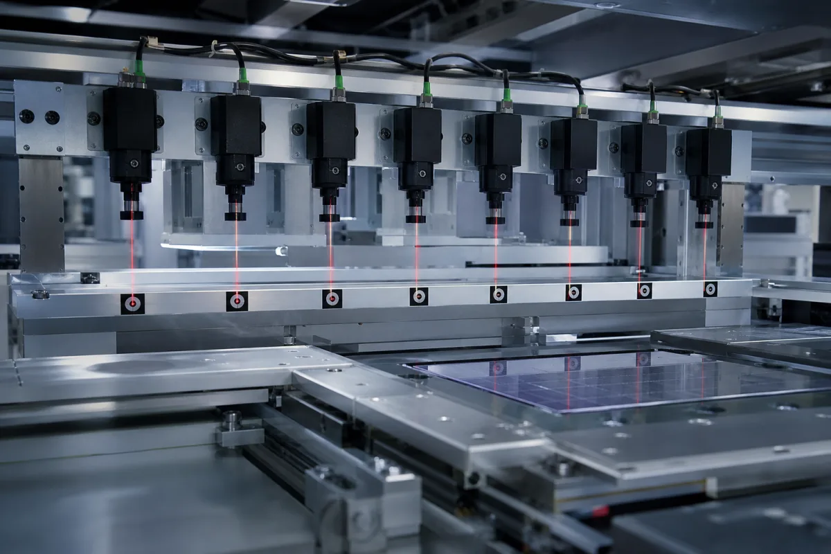
Alignment sensor array: a row of point laser displacement sensors on a fixed beam that reads all measuring points at once
Point laser heads fixed side by side on one beam · simultaneous height readings for flatness, warpage and level, a datum plane from three points, and synchronised or alternating triggering
Instead of moving one sensor across a part, an alignment sensor array puts point laser displacement sensors side by side on a rigid beam, each aimed at its own spot. One trigger gives a height at every spot, and the software turns those heights into flatness, warpage, tilt or level. What makes such an array work is not the single sensor but how the heads are spaced, synchronised, zeroed against one reference and combined into one result.
Fixed multi-head arrays of point laser displacement sensors, with their mounting beam, synchronisation wiring and evaluation software, used to measure flatness, warpage, level and alignment of panels, substrates, plates and assemblies at all measuring points simultaneously. Single-point laser triangulation sensors chosen on their own are covered on the Laser triangulation height sensor for part and gap measurement page; 2D/3D laser line profile scanners on the Laser scanner module page; side-by-side photoelectric presence sensors on the Sensor array of side-by-side photoelectric sensors page; and laser heads for aligning coupled shafts on the Laser alignment module for shaft alignment page. Confocal and interferometric gauges are outside this page.
CNFX editorial research · Sources checked October 13, 2026 · 3 sources
Why fix one head per point instead of moving one: cycle time against hardware count
Keyence sets out the two ways of measuring warpage and flatness with laser displacement sensors. With one head at each location, flatness comes from the height differences between them; no head moves, so there is no chattering error from motion, no moving mechanism and a short inspection cycle. With one head, the target or sensor has to be moved and the result is built from readings at each location; that saves heads but adds the mechanism and the motion errors. Its LK-G triangulation series is listed with a sampling rate up to 392 kHz and 12 connectable sensor heads. [1]
The display-panel flatness patent from Wuhan China Star Optoelectronics describes both layouts in one device: a single laser head moved at set intervals to each marked point, or one laser head per point, all emitting at once so that every point is measured in a single step. [3] Editorial calculation: with the patent's eight points, a moving single head needs eight positioning moves and readings per panel, while an eight-head array needs one trigger; the array's cost is eight heads and their wiring.
The image shows eight cylindrical laser sensors in a row on an aluminium beam, each projecting a red spot onto a target mark, with a solar cell panel on a stage below. Ask how the supplier fixes and zeroes each head on the beam, and how the beam's own straightness is checked.
02
Turning eight heights into one flatness value: datum plane through three points
In the Wuhan China Star patent, eight points are marked on an LCD glass substrate or polarizer, four near the edge and four near the centre. The computer fits a datum plane through three of the measured heights, calculates the distance from that plane to each of the remaining five points, and reports the largest distance as the board's surface flatness. [3]
The patent reports a measurement precision of 0.001 mm and a repetitive measurement error held within 3 µm, against about 0.1 mm for the feeler-gauge and steel-rule methods on a marble table that it replaces; results are saved automatically for whole batches. [3]
Editorial note: a three-point datum plane is one way to define flatness from discrete points; the value changes if the software fits a plane through all points or reports the spread above and below it. Ask which calculation the array software applies, which points define the reference, and whether the result is compared against a master part measured the same way.
03
Choosing the heads: range, linearity, spot size and how neighbours are triggered
Micro-Epsilon's optoNCDT 1900 data sheet shows the figures that decide head choice for an array, and its synchronisation input shows how heads on one beam are coordinated: an RS422 input set to trigger, sync, master/slave or master/slave alternating, so that heads measure simultaneously or alternately. [2]
The data sheet gives repeatability as a typ. value at 4 kHz with a median of 9, that the measuring rate is adjustable from 0.25 to 10 kHz, and that all data apply to a white, diffuse reference ceramic. The heads are laser class 2 at 670 nm, tolerate 50,000 lx ambient light, run on 11–30 V DC at under 3 W, are IP67, operate at 0 to +50 °C, and give 4–20 mA or voltage analogue output and RS422 digital output, with PROFINET or EtherNet/IP through an interface module. [2] Editorial calculation: linearity of ±0.02% of full scale on the 10 mm model is 10 mm × 0.0002 = ±2 µm, matching the table.
Editorial note: on a panel whose surface is not the white reference ceramic, such as a solar cell or glass, each head's linearity and repeatability should be re-checked on a sample of the real surface, since the published values apply to the reference surface. [2] The spot sizes also set how close a measurement point can sit to a panel edge or a target mark.
For an array, specify how many heads, their spacing and stand-off, whether they fire together or in alternation, and which head or controller acts as master.
04
Part and point layout for an alignment sensor array
Paste it into your enquiry below or into an email to a maker, then replace every bracket.
Part: [panel, plate or substrate; size; surface (glass, cell, metal, painted)]
Points: [number; positions; edge distance]
Result: [flatness, warpage, tilt or level; datum definition; tolerance]
Heads: [measuring range; stand-off; spot size; linearity on the real surface]
Triggering: [simultaneous or alternating; master/slave; cycle time]
Output: [analogue, RS422, fieldbus; data logging per part]
Explore company information and manufacturing capabilities, then discuss the scope of your project with a relevant supplier.
Share this page
Compiled and source-reviewed by the CNFX editorial team.
Each manufacturer above links to the page on that company's own website where the product is listed, with the date we checked it. How we source and review
· Page last updated 13 October 2026
Buyer questions
Why fix one laser head per point instead of moving one head?
Keyence lists no motion-induced chattering error, no moving mechanism and shorter inspection cycles for fixed multi-head setups; a single moving head saves sensor cost. [1]
How is flatness calculated from point heights?
In the Wuhan China Star patent, a datum plane is fitted through three of eight measured points and the largest distance from it to the other five is the flatness. [3]
How are neighbouring laser heads coordinated?
Micro-Epsilon's ILD1900 has an RS422 synchronisation input for master/slave or master/slave alternating operation, so heads measure simultaneously or alternately. [2]
How precise can a laser flatness array be?
The display-panel patent reports 0.001 mm measurement precision with repeat error within 3 µm; a single ILD1900-10 head lists repeatability below 0.4 µm (typ.) on a reference surface. [3][2]
Sources and what still needs a direct check
Sources checked 2026-10-13. A Keyence application note on multi-head versus single-head flatness measurement, the Micro-Epsilon optoNCDT 1900 data sheet, and a Wuhan China Star Optoelectronics patent on laser flatness measurement of display substrates.